


15
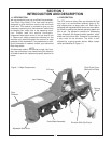
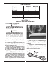
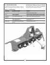
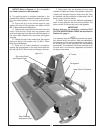
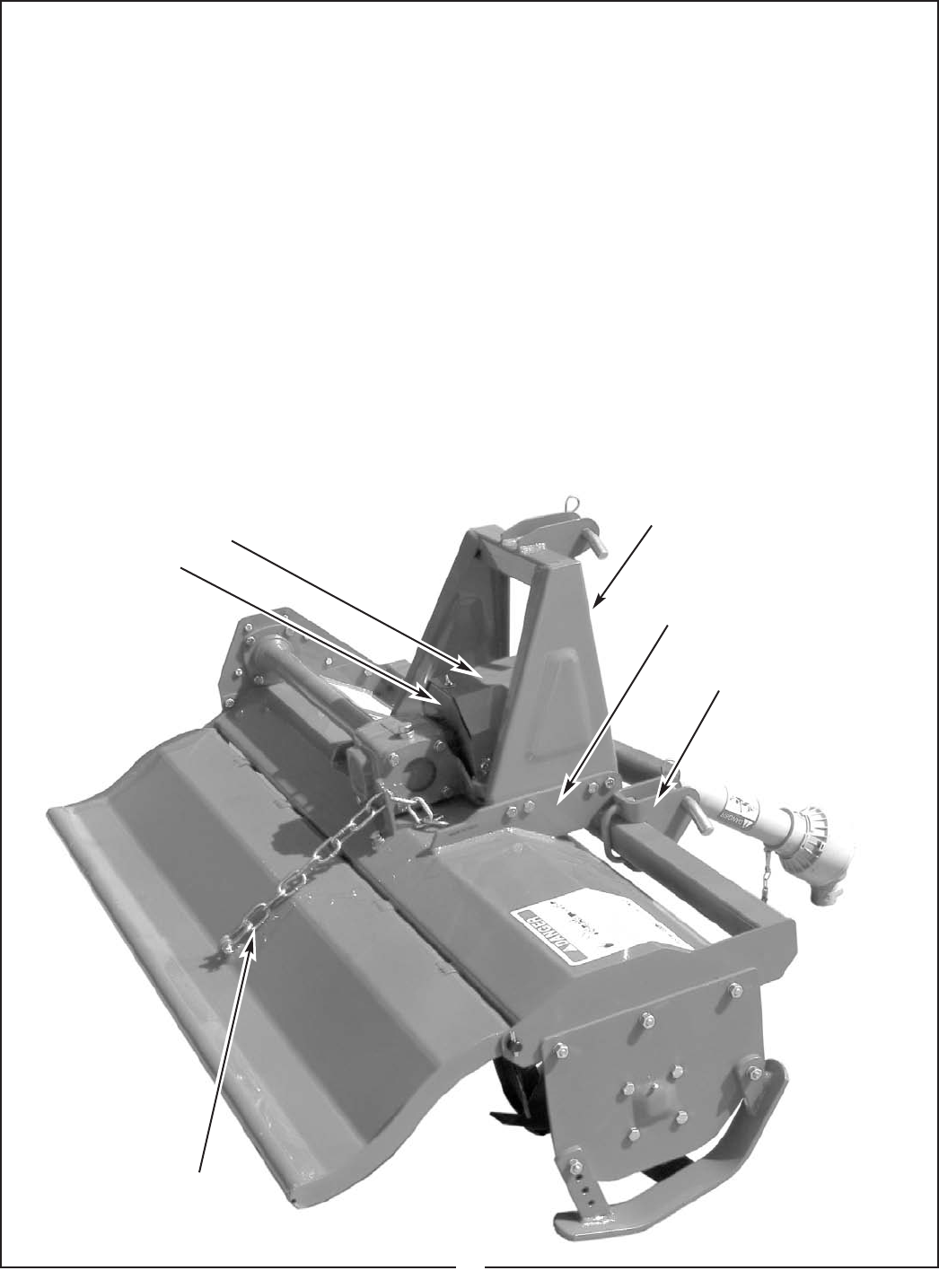
Figure 5-1
“A” Frame
Slip clutch Shield
and Support Plate
Strongback
Lower Hitch Pin Bracket
Rear Deflector
Adjustment Chain
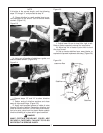
F. Place lower hitch pin brackets on front cross
member of frame and fasten into position using M12
U-bolts and flanged locknuts. Notice that the hitch
pin brackets can be positioned to best match the lift
arms on your particular tractor.
G. Attach one end of rear deflector adjustment
chain to rear deflector with the clevis provided. The
other end will fit into the slot next to the gearbox.
IMPORTANT
Before delivery to customer, perform SLIP
CLUTCH OPERATIONAL CHECK as described in
Section 4-4, page 11.
NOTE
It is important that the customer receives this opera-
tor’s manual with his machine. Safe and satisfactory
performance of this machine depends on the opera-
tor knowing the correct operating and maintenance
procedures. The customer should be reminded to fill
out and mail in the warranty registration card within
ten days of purchase.
NOTICE: Refer to Figures 1-1, 3-1, 4-1 and 5-1
for visual reference to aid assembly.
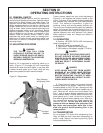
A. The parking stand is shipped installed in the
upside down position. Remove the stand and replace
it in the correct position. Pin into the “parked” posi-
tion.
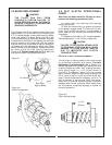
B. Place the slip clutch shield support pate
against the front of the gearbox and fasten with(4)
M8 x 16mm bolts and lockwashers .
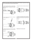
C. Remove the cross bolt from the end of the slip
clutch. Slide the slip clutch onto the gearbox input
shaft and align the cross bolt hole with the groove in
the input shaft. Replace the cross bolt and tighten
securely .
D. Position the slip clutch shield over the support
plate and fasten into position with (3) M8 x 16mm
bolts and lockwashers.
E. Place the “A” frame weldment into position
against the strongbacks on the main frame and fas-
ten with (8) M10 x 35mm bolts and flanged locknuts.