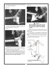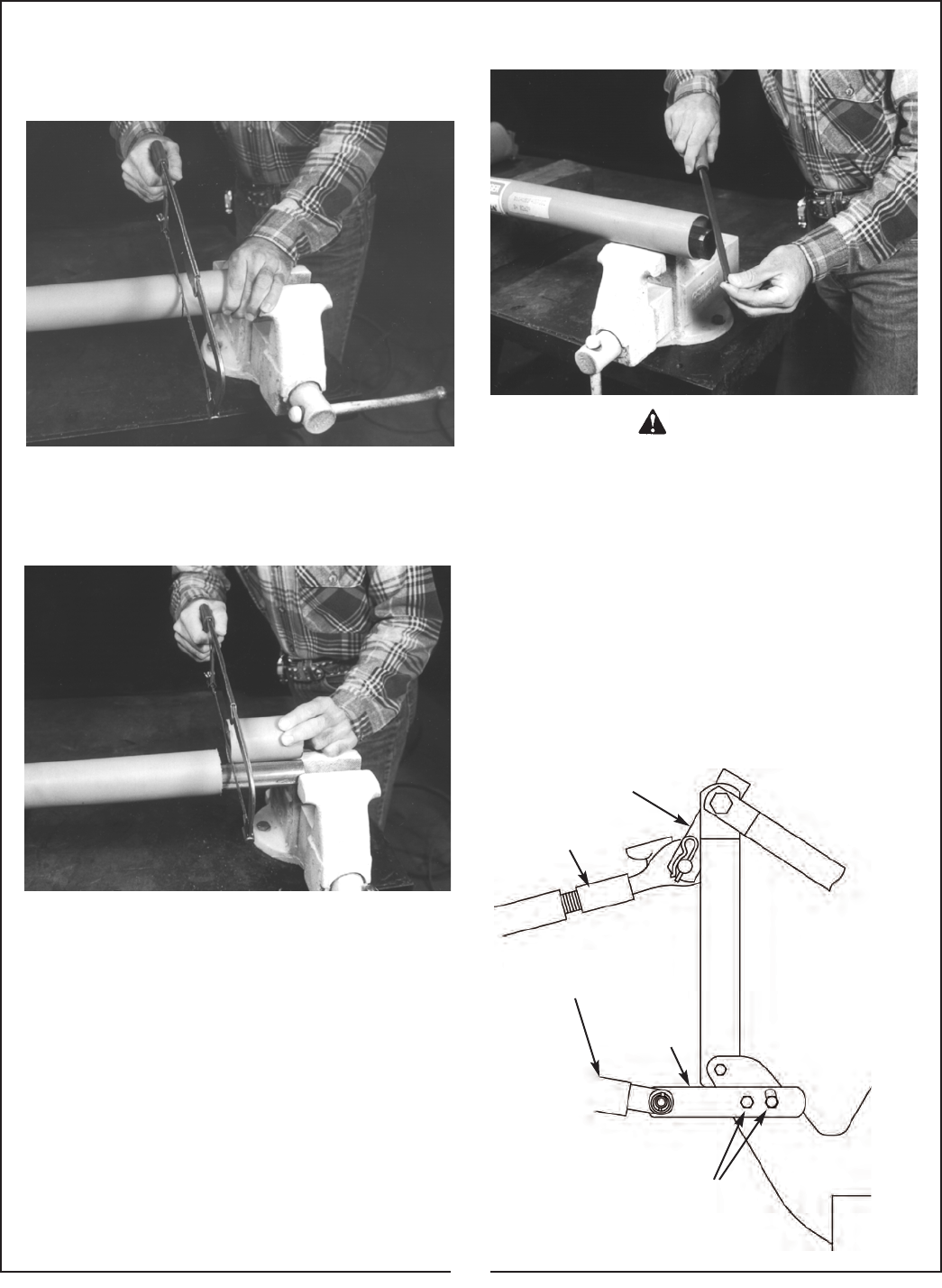
G. Clamp end of driveline in a vice. Cut off shield
where marked. (Figure 2-3).
Figure 2-3
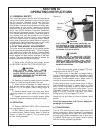
H. Using cut off section of shield as a guide, cut
shaft the same amount. (Figure 2-4)
I. Repeat steps “G” and “H” to other driveline sec-
tion.
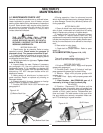
J. Deburr ends of driveline sections and clean
away all chips and filings. (Figure 2-5)
K. Apply multi-purpose grease to outside of male
driveline section. Assemble driveline and install on
tractor and cutter. Pull on each driveline section to
be sure yokes lock into place. Make certain driveline
shielding is in place and in good condition.
Figure 2-4
Figure 2-5
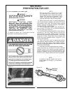
MAKE CERTAIN DRIVELINE YOKES
ARE SECURELY FASTENED. FAILURE
TO DO SO MAY RESULT IN SERIOUS
INJURY.
L. Raise cutter off ground and adjust lower lift
arms to level cutter right to left. Refer to tractor oper-
ator’s manual.
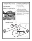
M. Lower cutter to work position. Adjust tractor
top link to position cutter top flex link as shown in
Figure 2-6. This allows cutter to “float” during opera-
tion.
N. Adjust tractor sway chains, stabilizer bar or
equivalent to prevent side sway.
DANGER
9
Tractor
Top Link
Tractor
Lower Lift Arm
Lower
Link
Figure 2-6 Flex-Link
These bolts should be tightened
“snug”, but loose enough to allow the
link to pivot.


