


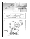
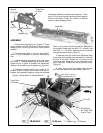
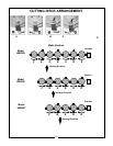

Mainframe assembly unfolded from cutter bar. Three
point lift hitch and parking stand have been assem-
bled to mainframe. Cutter bar remains in bottom
section of steel shipping frame.
Figure 2
Mainframe
Support Leg
Three Point
Lift Hitch
Cutter Bar
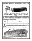
ASSEMBLY
1. Unbolt steel shipping frame. (Figure 1) These
frame members will be discarded. Remove plastic
wrapping and cut wiring that holds loose pieces
together.
2. Arrange loose parts on floor for easy identifi-
cation. Lay out fasteners in groups according to
size.
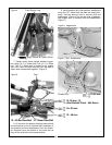
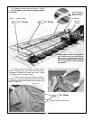
3. Unfold mainframe assembly from over cutter
bar. Install “T” shaped support leg up through main-
frame and pin in place to support the mainframe.
Replace nut and bolt in top of support leg. (Figure 2)
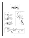
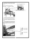
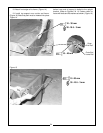
4. Remove threaded block from inside of “U”
bracket. Slide the three point lift frame over the “U”
bracket and assemble together using the threaded
“U” Bracket
Pivot Pin
block on the inside and the two square washers on
the outside. Fasten with two M16 x 2 - 40 bolts. Use
two M16 x 2 - 35 bolts, flatwashers and locknuts
through the vetical hloes. (Figure 3)
5. Remove pivot pin from end of mainframe tube.
Insure that the threaded plug is screwed in flush with
the end of the tube. Fasten the “U” bracket to the
mainframe tube using the pin and flatwasher previ-
ously removed. Grease the sliding contact points.
(Figure 3)
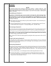
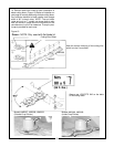
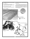
6. Insert and pin the front support leg into posi-
tion to further stabilize the mainframe. (Figure 4)
Apply Grease At
Contact Points
A
B
16-40 mm
16-35 mm
Bolt Block Inside of
Frame With Bolts “A”.
“T” Support Leg “U” Bracket
Pivot Pin
Figure 3 Tighten Bolts “A” Before Bolts “B”
48
Plug Should
Be Flush With
End Of Tube
Three Point
Lift Frame