


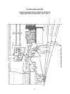
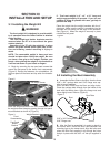
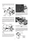


D. Place the lower frame assembly to the ends of the
frame bracket s as shown in (Figure 10). Use Four 3/8”
x 3/4” bolts and 3/8” Nyloc locknuts from the hardware
package.
Figure 10
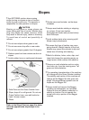
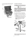
3-4 Installing the Top and Inlet Tube
A. Place the top assembly on the upper frame
assembly so the hinge areas are located between the
hinge lugs on the upper frame assembly. Align the
holes and insert a 5/16” x 2-1/2” bolts and two 5/16”
nyloc nuts. Do not overtighten the nut, the top
assembly should raise and lower freely. Refer to
(Figure 12).
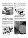
Figure 12
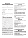
B. Locate the inlet tube and install to the top assem-
bly. To install raise the lid and place the smooth end of
the tube through the hole. Push the tube through the
hole and firmly apply pressure until the lip has seated
against the inside of the top. Refer to (Figure 13)
Lower Frame
Assembly
3/8” x 3/4” Bolts
3/8” Nyloc Locknuts
Frame Bracket
Ends
5/16” x 2-1/2 bolt
5/16”Nylock nut
Top Assembly
Hinge Lugs
Upper
Frame
Assembly
Figure 13
C. After the inlet tube is in place attach the 6” hose to
the inlet tube and the boot assembly. Use the two large
hose clamps supplied in the bag of hardware. For best
collection results, trim hose so there is no more than 2
inches excess hose with mower deck in the lowest
position. Refer to (Figure 14).
Figure 14
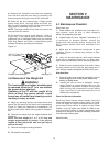
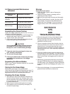
3-5
Installation / Removal of Collection
Bags
A. To install the bag onto the ring, first install the ring end caps
onto both ends of the ring. Place the seam openings of the bag
onto the bag ring openings and slide the bag around the ring
until the bag is completely on the ring. Continue to slide the bag
around the ring until the seam opening in the bag is opposite
the gap in the bag ring. Refer to (Figure 15)
Top Assembly
Inlet Tube
Inlet Tube Lip
Hose Clamps
Ring End Caps
Bag Ring
Location of
Bag Ring End
Caps after
installation
(Under Fabric)
Figure 15
12