


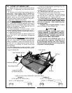


5-2 3-POINT LIFT MODELS (287)
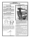
A. Attach A-frame struts to mounting brackets
using 5/8” x 2” capscrews and locknuts as shown.
(Fig. 5-1)
B. Place flex link and pivot tube between top of A-
frame struts. Place support yokes on outside of A-
frame struts. Fasten together using a 5/8” x 6” cap-
screw and locknut. Attach the opposite ends of the
support yokes over the welded strongback tubes
which are located closest to the gearbox using 5/8” x
8” capscrews, flatwasher and locknut.
C. For single tailwheel mounting, position tail-
wheel bracket on rear of cutter deck as shown. (Fig.
5-1) Align holes in tailwheel weldment with holes in
support yokes and strongback tubes (tubes located
closest to the gearbox). Fasten with the 5/8” x 8”
capscrews, flatwasher and locknut.
D. Place flatwasher on wheel spindle. Install
wheel on tailwheel weldment securing with roll pin.
E. Bolt adjusting bracket to cutter deck using 5/8”
x 2” capscrew and locknut.
F. Place tailwheel frame into desired position and
fasten with 1/2” x 1-3/4” capscrews, lockwashers
and nuts.
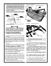
G. For mounting dual tailwheels, position tailwheel
bracket at the rear tubes located in the strongbacks.
(Fig. 5-2) Align holes in tailwheel weldment with
holes in strongback. Install pivot bushings and fas-
ten with 3/4” x 8” capscrews and flange locknuts.
Pin ratchet or lift cylinder (8” stroke) to axle and
deck assembly.
H. Place flatwashers on wheel spindles. Install
wheels on tailwheel weldment securing with roll pins.
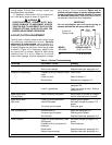
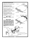
I. Install lift pins and spacers according to Fig. 5-3.
Fasten lift pin with klick pin.
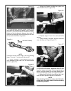
J. Attach clutch shield to gearbox as shown in
exploded drawing in Figure 5-6.
K. Remove pivot bolt from spline end of clutch.
Remove inspection cover from clutch shield.
L. Slide clutch onto gearbox input shaft aligning
bolt hole with slot in input shaft. Fasten with pivot
bolt, lockwasher and nut. Torque to 30 ft./lbs.
M. Loosen eight nuts retaining clutch springs
1/3 turn or until spring can be turned with fingers.
N. With tractor at idle speed, engage tractor
PTO drive 2-3 seconds. Clutch should slip with-
out turning blades.
O. Retighten nuts to original position. If adjust-
ment is necessary, refer to Section 4-6.
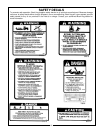
OVER-TIGHTENING SPRING NUTS MAY
CAUSE DAMAGE TO IMPLEMENT AND/OR
TRACTOR DUE TO INCORRECT SLIP CLUTCH
TORQUE SETTING. ALWAYS FOLLOW THE
PROPER ADJUSTMENT PROCEDURE.
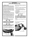
P. Fill gearbox with EP80W-90 gear oil to
check plug on rear of gearbox. Allow time for oil
to seep through bearings into lower housing.
Replace temporary plug with vent plug supplied
in operator’s manual package.
WARNING
Category I
(2-7/8” Spacer not used on Cat. I)
2-3/4” x 1-1/2” Spacer Used
Category II
2-7/8” x 1-1/8” Spacer
2-3/4” x 1-1/2” Spacer
16
Figure 5-3 Front View of Model 287 Lower Hitch Points
Figure 5-2 Model 287
Lift Pins
Driveline
Hydraulic Cylinder
(Or Ratchet Adjuster)
Tailwheel Assembly
Rear Safety Chains
Dual Tailwheel Bracket
Clutch Shield