


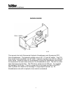
Commercial Snowblower
11
ASSEMBLY INSTRUCTIONS – cont’d.
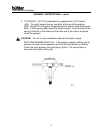
b) Using tape or a bright colored marking pen, mark on the outer
shields the position where the shaft is completely pushed together
and the position where you have a 4” overlap. Watch these marks
when moving the blower through all possible operating angles to
see that the PTO shaft stays within this range.
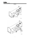
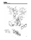
c) With the engine on the tractor shut off, attach the PTO shaft. The
tractor end has a standard 6-spline end with a spring loaded locking
collar. The snowblower end has a clamp-style yoke with a 3/8” key
way. Slide the yoke onto the gearbox shaft with the 3/8” key
supplied. Lock the yoke in place with the ½” x 3” bolt and lock nut
fitted through the groove in the gearbox shaft. After tightening the
bolt, insert and tighten the 3/8” socket set screw supplied.
Caution: Always check to see that both ends of the PTO shaft are securely
attached every time the Snowblower is used. This should always
be done with the tractor engine off.
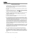
d) Check that the PTO shaft does not bottom or separate with the
blower in the extreme high and low positions. A longer optional
PTO shaft is available if the standard shaft is too short. Check for
free movement of all parts in various raised positions; particularly
the PTO shaft.
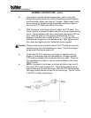
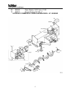
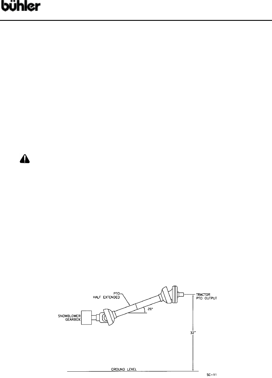
e) NOTE: Excessive U-joint wear and shear pin failure may result if
the tractor PTO angle exceeds 20º. The drawing below gives an
approximate way to check this angle. With the PTO half extended,
the tractor output should not be over 32 inches high. Use 34 inches
if the PTO is nearly compressed.