


Commercial Snowblower
10
ASSEMBLY INSTRUCTIONS
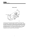
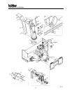
1. SPOUT ASSEMBLY FOR ALL SNOWBLOWERS: Remove two of the
grooved spout rollers to mount the discharge spout. Replace the two rollers
to hold spout in place. Install the 2 ½” x 8” cylinder on the spout using the
pins supplied.
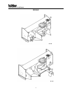
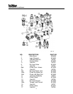
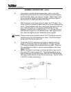
2. HYDRAULIC DRIVE: The 62” long hydraulic lines (#14) for the spout
deflector cylinder should be connected to the two ports on the hydraulic block
labeled C1 and C2 (see section on hydraulic control block for block drawing).
The 30” long lines (#15) from the spout control motor connect to the two ports
labeled M1 and M2 on the hydraulic block. The ¾” diam. x 84” main
lines (#21) connect to the implement. NOTE: The customer must supply the
appropriate tips to connect the main lines to the implement. A two-piece
wiring harness is supplied with all hydraulic snowblowers. The 45” part of the
harness is mounted on the snowblower. One end of this wire connects to the
control block. The plug end mounts on a bracket welded to the top edge of
the quick hitch. The 155” part of the harness with the switch is connected to
the plug on the harness mounted on the snowblower. A switch mounted in
the cab controls the spout and the deflector. The alligator clips attach to the
battery which acts as a power source. A schematic of the wiring harness is
included in this manual.
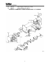
3. PTO DRIVE:
1. Slide the two hitch adaptor weldments (#17) into the sleeves on the body.
These tubes are adjustable to three different positions. The correct position
for each individual tractor will be determined when mounting the snowblower
on the tractor (see section on mounting blower on tractor). Start with the
tubes pulled out to the last hole. Connect to the snowblower using pins (#71)
and linch pins (#73).
Mount the hitch Weldment (#7) to the body. The top arm of the hitch bolts on
top of the bracket on the body using a ¾” x 1 5/8” bolt, lock washer and hex
nut. The bottom of the hitch bolts to the outside of the two hitch adaptors
using 5/8” x 1 ¾” hex bolts, flat washers, lock washers and hex nuts.
2. Connect two 108” hoses (#76) to the hydraulic spout control motor and
two hoses to the cylinder on the discharge spout. Connect these hoses to the
tractor after mounting the snowblower on the tractor.
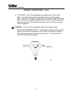
3. Mounting blower on tractor:
a) The pins supplied with the snowblower are for a category 2 quick
hitch. The quick coupling hitch has two holes both at the top of the
hitch and at each lift arm. When using a quick coupler, the pins
must be in the inside set of holes. Use the outside set of holes
with a standard three-point hitch.