


Heavy Duty Finishing Mower
8
HITCH ASSEMBLY INSTRUCTIONS
1. The hitch is assembled except for the two pivot bars (#69). Bolt one end of each
pivot bar between the welded brackets at the back of the deck using the bolts
assembled in the mower.
2. Remove the 3/4” bolt (#63) at the top of the hitch assembly. Using the same bolt,
assemble with the pivot bars between the hitch weldment (#38)
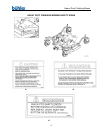
CHAIN KIT ASSEMBLY
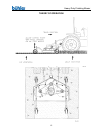
1. Drill 13/32” holes in the back lip of the deck Weldment spaced as shown on the
drawing. The hole spacing should be centered across the width of the back lip.
2. With the narrow lip of the chain guard plate (#2) turned up, push an end link of a
3-link chain up through the slot nearest the end of the guard plate. The chain rod
(#3) slides through the chain link along the top surface of the chain guard plate.
Slide through each chain in order along the entire guard place. Slide a flat
washer on each end of the rod. Hold the assembly in place with a 1/8” x 1” cotter
pin (#8) at both ends of the rod.
3. A 5/8” long spacer (#6) fits between the guard plate and the rear lip on the deck.
These spacers must be centered on the holes in the guard plate and the rear lip
on the deck. With the spacers in place, position the chain guard assembly under
the lip on the deck. Clamp on assembly to hold in place. Bolt guard plate
assembly to the deck using 3/8” x 1 ½” bolts, lock washers and hex nut.
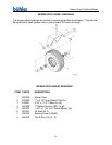
QUICK HITCH KIT INSTRUCTIONS
1. Remove the two sets of lift brackets with the lower lift pins from the mower
hitch arms (#4).
2. Bolt the adaptor plates (#13) to the outside of the hitch arms welded to the
deck. Turn the plates as shown in drawing. Use the ¾” x 2 ½” bolts and
bushings in the 1” holes. The 5/8” x 2” bolts holding on the a-frame weldment
are removed and replaced with 2 ½” bolts (#3) which also fit through the
adaptor plates. The bushings already in the a-frame must remain in place.
3. Assemble the two quick hitch arms (#4) on the inside of the adaptor plates
using the lift pins with the swivel bushings from step one at the bottom. The
a-frame and quick hitch arms are connected at the top using an adaptor
weldment (#11). With the welded bushings on the adaptor facing down, the
a-frame is attached using the top link pin (#9). The hitch arms (#4) are bolted
on using a ¾” x 4 ½” bolt (#1) which fits through a 2 3/8” spacer (#12).