


1.9 RECONFIGURING THE
FUEL SYSTEM
1.9.1 15KW, 990CC ENGINES
To reconfigure the fuel system from NG to LP, follow
these steps:
NOTE:
The primary regulator for the propane supply is
NOT INCLUDED with the generator. A fuel pres-
sure of 11 to 14 inches of water column (0.4 to
0.5 psi) to the fuel inlet of the generator MUST
BE SUPPLIED.
1. Turn off the gas supply. (if connected)
2. Open the roof and remove the door.
3. Remove the battery. (if installed)
4. Remove the engine air in baffle located on the left-
hand side of the battery compartment. Two M6
screws are located on top of the baffle and two
M6 screws are located on the inside of the baffle
towards the back.
5. Remove the small hose clamp and hose from the
fuel regulator. It may be necessary to pry the hose
off of the brass fitting using a screwdriver to gen-
tly lift up the hose edge.
6. Remove the small brass hose fitting from the
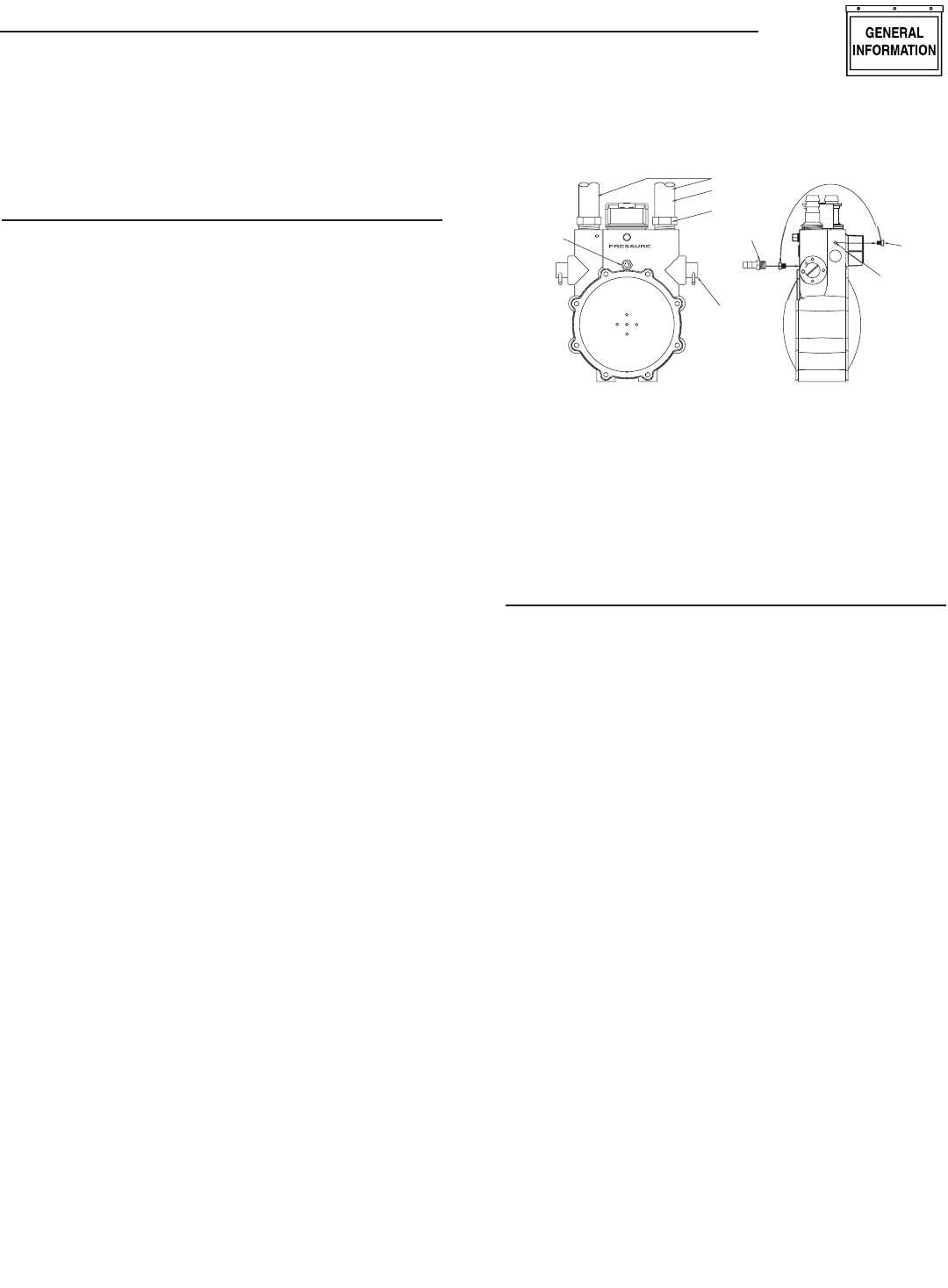
regulator casting.
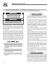
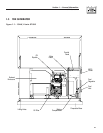
7. Place the small fuel jet, thread side first, into the
threaded hole originally occupied by the brass
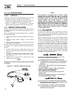
hose fitting (Figure 1.2).
8. Using a short No. 2 Phillips screw driver, thread
the small fuel jet into the regulator casting. Do
not over tighten.
9. Apply thread sealant to the threads of the hose
fitting and replace it into the regulator body.
10. Re-attach the small hose and hose clamp and
tighten as necessary.
11. Replace the engine air in baffle using the four M6
screws.
12. Identify both brass adjustment screws on the
regulator.
NOTE:
One adjustment screw can be accessed from the
front of the unit and the second can be accessed
from the back of the unit enclosure by removing
the plastic hole plug. The screw can be turned
with a long flat blade screwdriver.
13. To adjust the system to run on LP fuel, turn
BOTH adjuster screws 1/2 TURN CLOCKWISE.
The system should now be set for maximum
power and best performance. DO NOT, UNDER
ANY CIRCUMSTANCES, REMOVE THE SET
PINS FROM THE REGULATOR HOUSING.
THIS WILL VOID THE WARRANTY.
Figure 1.2 - Demand Regulator
BRA
SS
H
OS
E
FITTIN
G
IDLE
C
IR
CU
I
T
P
O
R
T
U
1
T
TAP
1
/8
NP
T
BRA
SS
H
OS
E
FITTIN
G
F
U
EL H
OSE
S
MAL
L
F
U
EL
J
E
T
RE
GU
LAT
OR
H
OUS
IN
G
P
O
R
T
AD
JUS
TE
R
SC
REW
S
OU
TLET P
O
RT
S
14. It may be necessary to make minor adjustments
to the preset adjustment screw settings to achieve
maximum power, particularly at higher altitudes.
If experiencing problems with the unit producing
maximum power, follow the procedure in Section
2.6 (Adjusting the Fuel Regulator).
1.10 LOCATION
1.10.1 GENERATOR
Install the generator set, in its protective enclosure,
outdoors, where adequate cooling and ventilating air
is always available. Consider these factors:
• Install the unit where air inlet and outlet open-
ings will not become obstructed by leaves, grass,
snow, etc. If prevailing winds will cause blowing or
drifting, consider using a windbreak to protect the
unit.
• Install the generator on high ground where water
levels will not rise and endanger it.
• Allow sufficient room on all sides of the generator
for maintenance and servicing. A good rule is to
allow three feet of space on all sides.
• Where strong prevailing winds blow from one
direction, face the generator air inlet openings to
the prevailing winds.
• Install the generator as close as possible to the fuel
supply, to reduce the length of piping.
• Install the generator as close as possible to
the transfer switch. HOWEVER, REMEMBER
THAT LAWS OR CODES MAY REGULATE THE
DISTANCE.
• The genset must be installed on a level surface.
The base frame must be level within two (2) inches
all around.
Section 1 — General Information
15 kW Generator
7