


Section 3 — Operation
15 kW Generator
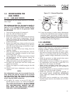
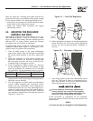
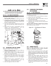
3.3.2 120 VAC GFCI OUTLET
The generator is equipped with an external 15 amp,
120 volt, GFCI convenience outlet that is located in
the right rear of the generator enclosure. When the
generator is running, in the absence of utility power,
this outlet may be used to power items outside a
home such as lights or power tools. This outlet may
also be used when utility power is present by run-
ning the generator in manual mode. This outlet does
not provide power if the generator is not running.
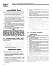
This outlet is protected by a 15 amp circuit breaker
located in the generator control panel (Figure 3.1).
3.4 SEQUENCE OF AUTOMATIC
OPERATION
The generator’s control panel houses a control logic
circuit board. This board constantly monitors util-
ity power source voltage. Should that voltage drop
below a preset level, circuit board action will signal
the engine to crank and start. After the engine starts,
the circuit board signals the transfer switch to acti-
vate and connect load circuits to the standby power
supply (load terminal lugs T1/T2 connect to terminal
lugs E1/E2).
Upon restoration of utility source voltage above a
preset level, generator circuit board action signals the
transfer switch to transfer loads back to that power
supply. After retransfer, the engine is signalled to shut
down.
The actual sequence of operation is controlled by
sensors and timers on a control logic circuit board,
as follows:
A. Utility Voltage Dropout Sensor
• This sensor monitors utility source voltage.
• If utility source voltage drops below about 70
percent of the nominal supply voltage, the sensor
energizes a 15-second timer.
• Once the timer has expired, the engine will crank
and start.
B. Engine Warm-up Time Delay
• This mechanism lets the engine warm up for
about 10 seconds before the load is transferred
to a standby source.
C. Standby Voltage Sensor
• This sensor monitors generator AC output volt-
age. When the voltage has reached 50 percent of
the nominal rated voltage, transfer to standby
can occur.
D. Utility Voltage Pickup Sensor
• This sensor monitors utility power supply volt-
age. When that voltage is restored to above 70
percent of the nominal source voltage, a retrans-
fer time delay starts timing.
E. Retransfer Time Delay
• This timer runs for about 15 seconds.
• At end of a 15-second delay, circuit board action
de-energizes the transfer relay in the transfer
switch.
• Retransfer to utility power source then occurs.
F. Engine Cool-down Timer
• When the load is transferred back to utility power
source, the engine cool-down timer starts tim-
ing.
• The timer will run for about one minute, and the
generator will then shut down.
3.5 MANUAL TRANSFER OPERATION
3.5.1 TRANSFER TO GENERATOR POWER
SOURCE
To start the generator and activate the transfer switch
manually, proceed as follows:
1. Set the generator’s AUTO/OFF/MANUAL switch to
OFF.
2. Set the generator’s main circuit breaker to its
OFF (or OPEN) position.
3. Turn OFF the utility power supply to the transfer
switch using the means provided (such as a utility
main line circuit breaker).
DANGER
Do not attempt to activate the transfer switch
manually until all power voltage supplies to the
switch have been positively turned off. Failure
to turn off all power voltage supplies may result
in extremely hazardous and possibly fatal elec-
trical shock.
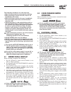
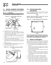
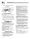
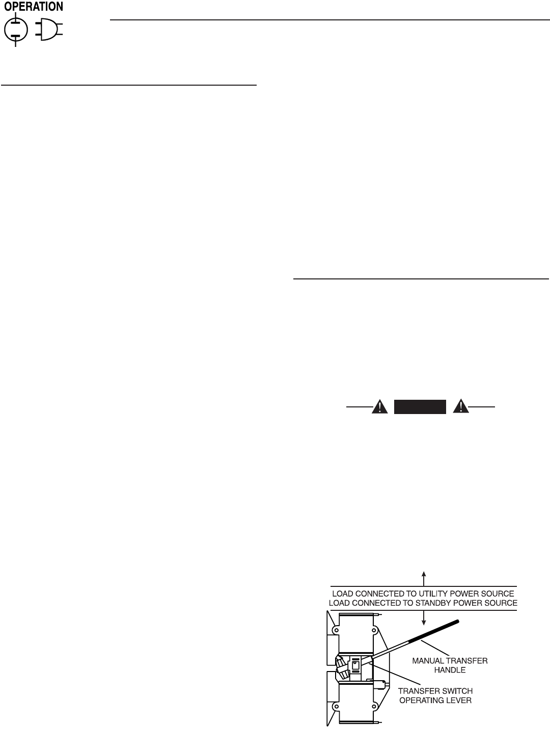
4. Use the manual transfer handle inside the trans-
fer switch to move the main contacts to their
“Standby”position, i.e., loads connected to the
standby power source (Figure 3.2).
Figure 3.2 – Manual Transfer Switch Operation
14