


SpA MC 2300
6
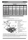
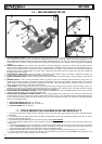
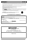
10 – DRIVES DESCRIPTION
A) CLUTCH CONTROL LEVER is used to disengage the engine from the tr ansmission, it must be operated ever y time you operate levers and
before stopping the machine. The lever is connected to the ENGINE-STOP (Ref. ”B” - Picture 5); To ignite the mac hine engage and lock the
clutch together with the l owered engine-stop, with the pushbutton outside the lever (Ref. “A” Picture 6). If the lever is not loc ked, the engine
will not start since it is earthed. To unlock the clutch lever it is sufficient to pull lightly the lever upwards and the locking will be automatically
released.
B) ENGINE STOP LEVER the main function of this safety device is to s top immediately the engine in the moment that one takes away his
hands from the handlebars and to loc k the clutch lever in engaged position ( disengagement of the engine from the dri veline organs ) in
order to prevent sudden starting of the machine during the ignition phase of the engine . If the clutch lever is not loc ked with the button
inside the engine-stop in engaged position, the engine, being connected to earth, will not start. The engine-stop is also used to switch off
the engine at the end of the wor k.
C) ACCELERATOR HAND-LEVER permits to increase or decrease the engine R.P.M. (power). By pushi ng it downwards cloc kwis e you
increase R.P.M.; by pushi ng it upwards countercloc kwise you decrease them.
D) WHEEL DISENGAGE LEVER is used to disengage the wheels from transmission. This lever helps to move the machi ne when switched
off.
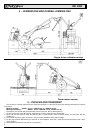
E) REVERSE LEVER is used to reverse the machine motion; by pulling the lever in the cultivator version towards the driving place, the
machine goes forwards, by pushing it for ward the machine goes backwards. The speed in the culti vator version is slower than in the lawn
mower version. A safety device does not allow to engage the reverse gear when the milling cutter is in motion. See Ref. ”A” Picture 8.
Before engaging the reverse gear disengage the milling cutter.
F) P.T.O LEVER is used to engage the power take-off to the different tools. By pushing the lever forward, in the lawn mower version, you
disengage the power take-off, by pulling it towards the driving place you engage it. In the cultivator version, by pushing forward you engage
the power take-off and by pulling the lever towards the driving place you disengage it.
G) HAND LEVER FOR HANDLEBAR LOCKING is used to adjust the handlebars in the most c omfortable position to wor k. Once you have
obtained the desired position, you have to tighten the hand lever.
H) HAND LEVER FOR STEERING COLUMN LOCKING is used to regulate sideways the handle and to 180° reverse the handle itself. By
unscrewing the hand lever you release the steering column, which can pi vot; once you have obtained the desired position tighten strongly.
To 180° reverse the steering column take off the reverse levers and P.T.O and put them on again. The hand lever is pawl oper ated (see
hand lever for handlebar loc king ).
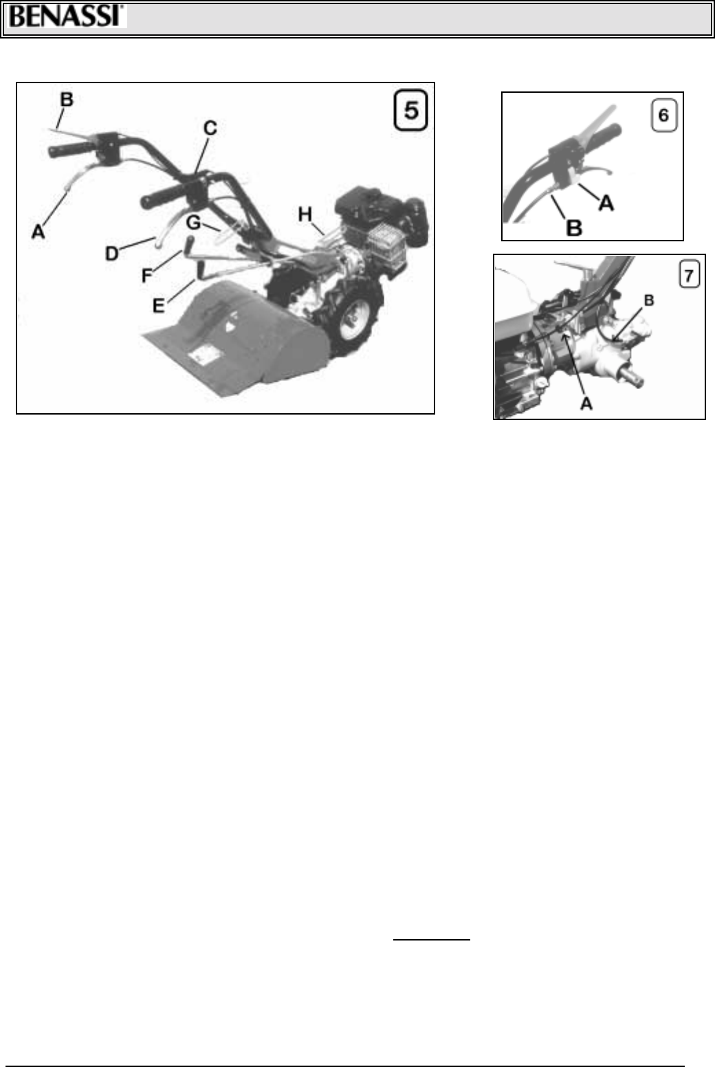
! FILLING AND VENT OIL CAP (Ref. ”A” - Picture 7).
! DISCHARGE GEARBOX OIL CAP. (Ref. ”A” Picture 14)
! LEVEL OIL SCREW (Ref. “B” Picture 7)
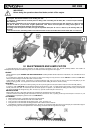
11- TOOLS MOUNTING AND MACHINE REVERSIBILITY
! It is ver y easy to mount or to c hange tools to the machine. Tools are all quic k coupling type and don’t need screws or fastening spanners
for the locking.
! Tools ar e coupled in the machi ne body ( male and female) and locked with a pin. The pin must be locked with the l ever (Ref. “B” Picture
8) in order to avoi d its disengagement.
! Assure that the tool part (male) to coupl e in the machine body is al ways well lubricated.
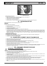
! To turn the handl ebar steering column from the Culti vator version (bac k tools) to the Power mower version (front tools) proceed in the
following way:
1) Take off the speed selec tor levers PTO completely, unscrew the hand lever steering column (Ref. “H” Picture 5), turn 180° the steering
column counterclockwise, tighten thoroughl y the hand lever and i nsert the levers again, not forgetting to lock them with its cotter pins,
making them pass through the two hol es with fairlead on the left of the handle support.
2) Take off the safety loc king rod for reverse gear, (Ref. “A” Picture 8), slippi ng off the two speci al cotter pi ns, (Ref. “C” Picture 8).
! To pass from the Power mower version to the Culti vator version proc eed in the same way, turni ng clockwise the steering column. Put
the safety loc ki ng rod for reverse gear again, (Ref. “A” Picture 8).