


500Z 26HP - 48” Mower Deck
TP 300-7368-IR-ZT-N
1/20084
Tractor
Assembly
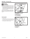
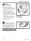
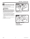
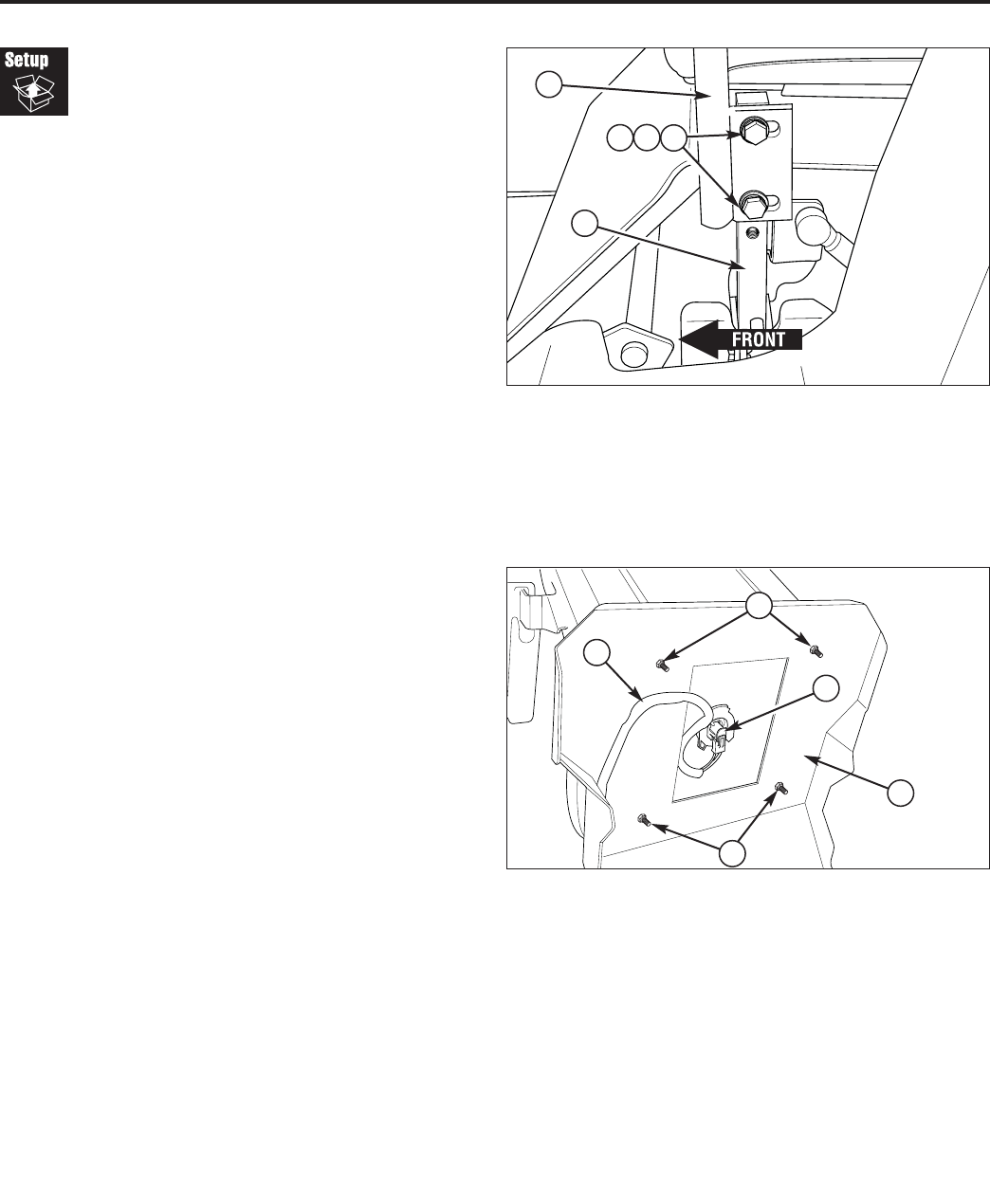
Install Ground Speed Control Levers
1. Install the ground speed control levers (A, Figure 3)
onto the control lever base (B) using the 5/16-18 x
3/4” bolts, 5/16” lock washers and 5/16” flat washers
(C, D & E). Prior to tightening the bolts, align the
handles with each other.
NOTE: There is a LEFT-HAND and a RIGHT-HAND
control lever. When assembled to the base, the lever
base should be pointing towards the rear as shown in
Figure 3.
Figure 3. Install the Control Levers
A. Ground Speed Control Levers
B. Control Base
C. 5/16-18 x 3/4” Bolt(s)
D. 5/16” Lock Washer(s)
E. 5/16” Flat Washer(s)
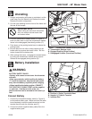
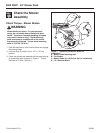
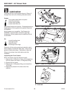
Figure 4. Remove The Existing Seat
A. 5/16-18 Nylock Flange Nuts
B. Wire Harness
C. Seat Mount Plate
D. Seat Switch
A
A
D
C
Seat Assembly
1. Unpack the seat.
2. Install the seat onto the seat mount plate (C, Figure
4) and secure with the 5/16-18 nylock flange nuts (A).
3. Connect the wire harness (B) to the seat switch (D)
that is located in the bottom of the seat.
B
E
D
C
A
B