


INSTALLATION
8
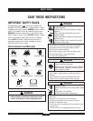
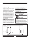
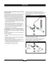
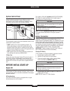
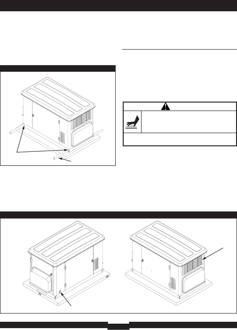
Two 48” lengths of 1” pipe (supplied by the installer) are
required to lift the generator manually. Insert pipes through
the lifting holes located near the unit’s base, as shown in
Figure 3.
You may also lift the unit using a “hook and hoist” method
attached to the lifting pipes, provided that you use a spreader
bar to ensure that the chains or cables do not touch the
generator’s roof.
After unit is in place, fill the lifting holes with the supplied
lifting hole plugs.
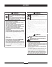
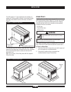
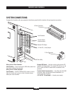
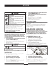
Access Doors
The Home Generator System is equipped with an enclosure
that has three access doors (Figure 4). The doors are named
for a significant component located behind them. Starting
with the side that has the fuel connection and proceeding
clockwise, the doors are named:
• Oil Fill door
• Control Panel door
• Oil Drain door
Each Home Generator System is equipped with two identical
keys. These keys fit the locks that secure the access doors.
To Open an Access Door:
1. Insert key into lock of access door you wish to open and
turn one quarter turn counterclockwise.
2. Grasp door’s handle and turn one quarter turn
counterclockwise to open. Remove key.
To lift: Insert
pipe here
Installer-supplied pipe
Figure 3 — Location of Lifting Holes
Oil Fill Door
Fuel Inlet
Exhaust
Port
Control Panel Door
Oil Drain Door
Exhaust Bulkhead
Figure 4 — Enclosure Access Doors
WARNING
Contact with muffler area can result in serious
burns.
• DO NOT touch hot parts and AVOID hot exhaust gases.
• Allow equipment to cool before touching.