


3
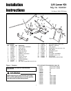
Lift Lever Kit Installation Instructions
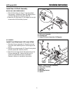
Figure 8. Install Lift lever Assembly
A. Lift Lever Assembly
B. Clevis Pin
C. Hair Pin
D. Mounting Bracket
E. Spacer
C
ALL MODELS
Install Front Attachment Lift Lever & Rod
1. Slide the lift lever assembly (A, Figure 8) on to the
end of the shaft assembly and on to the edge of the
tractor.
2. Secure to mounting bracket (D, Figure 8) using clevis
pins (B), spacer (E), and hair pins (C).
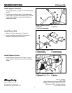
3. Slide lift rod (A, Figure 9) into the bottom hole in the
lift lever assembly (B). Secure with hair pin (C).
Install front attachment & hitch as outlined in
Operator’s Manual or Installation Instructions.
B
B
A
Edge of
Tractor
End of
Shaft
Assembly
D
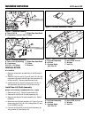
Install New Lift Shaft Assembly
BARON 2007 AND NEWER MODELS
1. Slide Lift Shaft Assy (A, Figure 7) into key-slotted
hole (existing - attached to frame (B)) aligning key in
Lift Shaft Assy (A) with key slot in hole (B).
2 Rotate the Lift Shaft Assy (C) 180 degree to the right
to secure the Lift Shaft Assy in place.
A
B
C
Figure 7. Install Lift lever Assembly
A. Lift Lever Assembly
B. Existing hole
C. Rotate Lift Lever Assembly 180 Degrees
E