


2
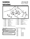
Installation Instructions Lift Lever Kit
INSTALLATION
ALL MODELS
1. Remove mower deck as described in the Operator’s
Manual.
2. Remove 5/16-18 nuts (A, Figure 2) and 5/16-18 x 3/4
capscrews (B) which hold the right rear seat deck (C)
to the frame(D). Discard capscrews and nuts.
3. Install bracket (E, Figure 3) using new 5/16-18 x 1-
3/4 capscrews (B) and new 5/16-18 locknuts (A).
Install New Lift Shaft Assembly
MODELS WITH SERIAL NUMBERS BELOW (<) 00999
1. Remove hair pin (F, Figure 5) and washer (E).
2. Remove lift rod (B) from lift shaft assembly (A).
3. Remove and discard lift shaft assembly (A). Retain
hardware.
4. Mount the new lift shaft assembly (A, Figure 6) to the
frame using four 5/16-18 x 3/4 carriage bolts (C) and
5/16-18 KEPS nuts (D).
5. Connect the lift rod (B) to the lift shaft assembly (A)
using washer (E) and hair pin (F).
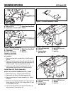
Figure 2. Capscrew Removal
A. Nuts, 5/16-18 C. Right Rear Seat Deck
B. Capscrews, 5/16-18 x 3/4 D. Frame
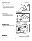
Figure 6. Install New Lift Shaft Assembly
A. Lift Shaft Assembly D. Nut, KEPS, 5/16-18
B. Lift Rod E. Washer
C. Carriage Bolts, F. Hair Pin
5/16-18 x 3/4
C
C
D
A
E
F
B
Figure 3. Bracket installation
A. Nuts, 5/16-18 (Existing) C. RIght Rear Seat Deck
B. Capscrews, D. Frame
5/16-18 x 1-3/4 (New) E. Bracket
A
D
B
C
A
D
B
C
E
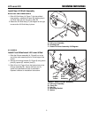
Figure 5. Remove Old Lift Shaft Assembly
A. Lift Shaft Assembly D. Nut, KEPS, 5/16-18
B. Lift Rod E. Washer
C. Carriage Bolts, F. Hair Pin
5/16-18 x 3/4
C
C
D
A
E
F
B
Figure 4. Lift Lever Assembly 1726404