


2-9
Power Steering Conversion Kit Installation Instructions
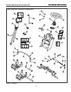
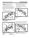
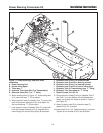
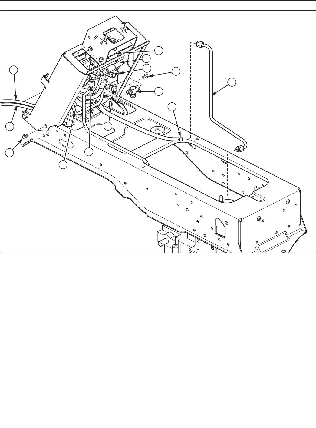
Figure 17 Power Steering & Hydraulic Hose
Installation
A. Power Steering Unit
B. Control Valve Spool
C. Three-way “T”
D. Hydraulic Tube (from Port P to Transmission)
E. Hydraulic Hose (Port T) to “T” fitting
F. Hydraulic Hose (Port P) to hydraulic tube
G. Hydraulic Hose (Port R) to steering cylinder
H. Hydraulic Hose (Port L) to steering cylinder
I. Hydraulic Hose (Port E) to control valve spool
J. Hydraulic Tube to Transmission from “T” fitting
K. Hydraulic Tube from spool to “T” fitting
L. Taptite Screws, 3/8-16 x 3/4
C
D
G
H
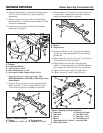
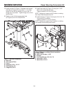
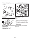
5. Attach existing tube (K, Figure 17), and existing tube
(J) to new three-way “T” (C) as shown.
6. Wrap hydraulic hose (E) (labeled “Port T”) around the
back of the power steering unit (A), and attach it to
the new three-way “T” (C) as shown.
7. Loop hydraulic hose (I) (labeled “Port E”) around the
front of the power steering unit (A), and attach the
hose fitting to the control valve spool (B) as shown.
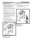
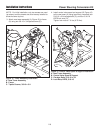
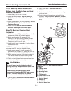
8. Route hydraulic hoses(G) and (H) (labeled “Port R”
and “Port L”) out the bottom of the bulkhead heat-
shield, and through the frame as shown in Figure 17
and Figure 19.
9. Attach hydraulic tube (D) to hydraulic hose (F)
(labeled “Port P”) as shown.
10. Install two 3/8-16 x 3/4 Taptite screws (L) as shown.
Tighten all four screws to 30 ft. lbs (40.8 Nm).
L
L
K
J
F
I
B
E
A