


2-4
Installation Instructions Power Steering Conversion Kit
A
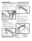
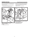
7. Remove front axle and steering linkage. See
SERVICE MANUAL, SECTION 8 - Steering & Front
Wheel Repair.
8. Remove J-hook (A, Figure 4) from original axle (B).
Save J-hook (A), 7/16-14 x 2 capscrews (C), and
7/16-14 lock nuts (D) for installation on new axle.
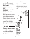
Figure 5 Spacer Removal
A. Spacer
B. Original Axle
B
Figure 4 J-Hook Removal
A. J-Hook B. Original Axle
C. Capscrews, 7/16-14 x 2 D. Lock Nuts, 7/16-14
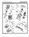
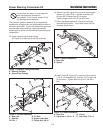
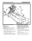
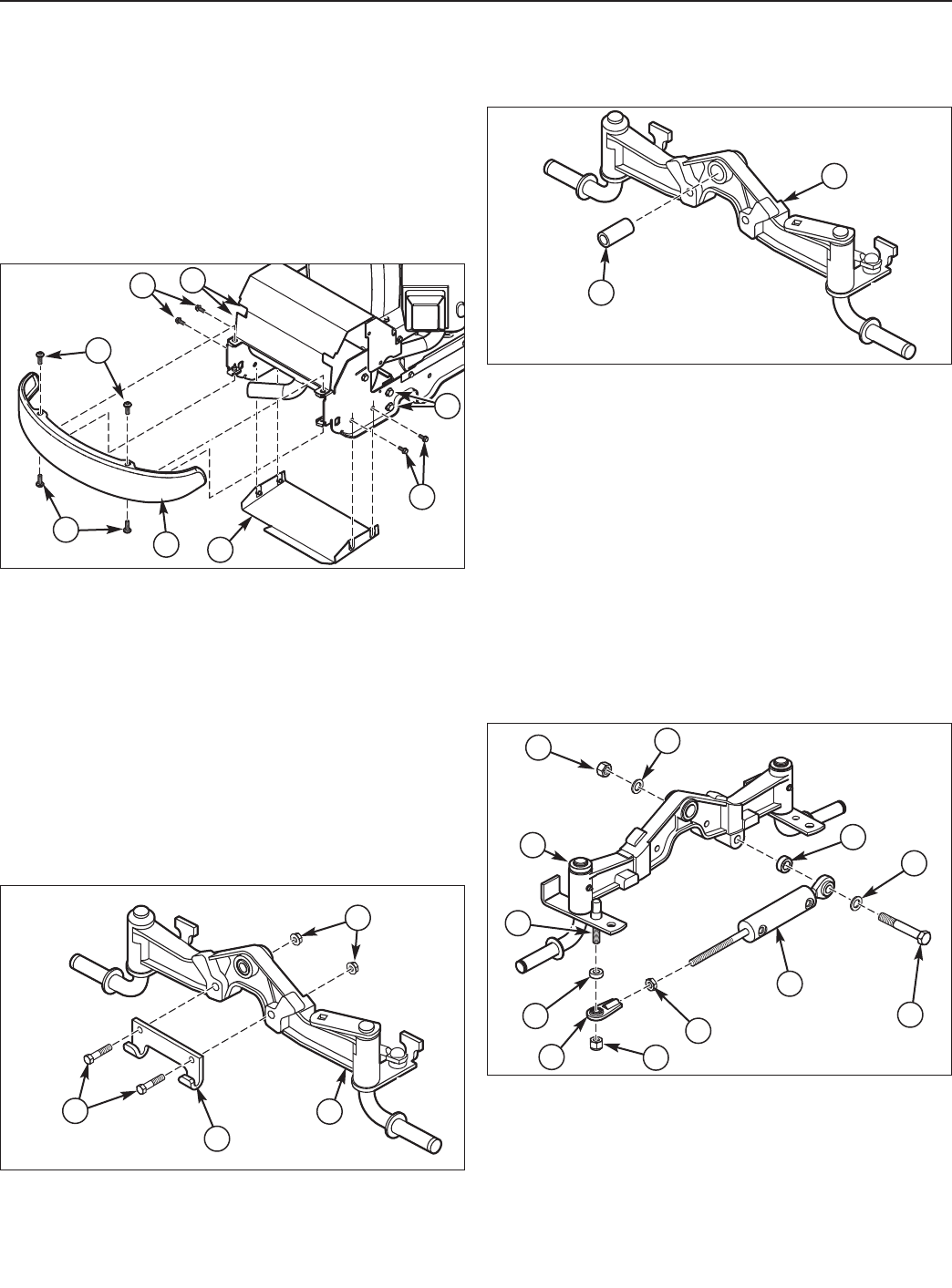
10. Thread 1/2-20 jam nut (D, Figure 6) onto steering
cylinder (B). Then attach ball joint (C) to steering
cylinder (B).
11 Attach spacer (E), ball joint (C), and 1/2-13 lock nut
(F) to mount (K) on axle as shown.
12. Attach steering cylinder (B) to axle (A) using
a M16 x 110mm capscrew (I), two 5/8 flat washers
(H), a spacer (G), and M16 lock nut (J) as shown.
13. Tighten lock nut (J) to 150 ft. lbs (203.4 Nm).
14. Tighten lock nut (F) to 48 ft. lbs (60.3 Nm).
A
B
D
C
J
H
A
G
B
H
I
K
E
D
C
F
Figure 6 Steering Cylinder Installation
A. New Axle B. Steering Cylinder
C. Ball Joint D. Jam Nut, 1/2-20
E. Spacer F. Lock Nut, 1/2-13
G. Spacer H. Flat Washer, 5/8
I. Capscrew, M16 x 110mm J. Lock Nut, M16
K. Mount, Ball Joint
A
B
C
C
D
D
E
E
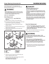
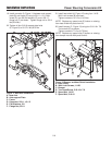
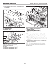
Figure 3 Bumper and Heat Shield Removal
A. Bumper
B. Lower Heat Shield
C. Torx Screws, 5/16-18
D. Whiz Lock Screws, 1/4-20
E. Whiz Lock Screws, Support Plate, 3/8-16
9. Remove spacer (A, Figure 5) from original axle cen-
ter mount (B). Inspect spacer for wear. Replace
spacer if excessive wear is indicated.
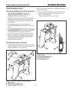
4.
Remove front bumper (A, Figure 3) by removing the
four 5/16-18 Torx screws (C). Save all parts for
reassembly.
5.
Remove muffler lower heat shield (B, Figure 3) by
removing the four 1/4-20 whiz lock screws (D). Save
all parts for reassembly.
6.
Loosen but do not remove all four 3/8-16 support
plate bolts (E, Figure 2).