


Document: - page 14 (Black)
Screen angle and frequency: 45.0000, 150.0000
14
MAINTENANCE
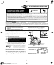
CLEANING DEBRIS
CAUTION: Do not use water to clean engine parts.
Water could contaminate fuel system. Use a brush
or dry cloth.
Engine parts should be kept
clean to reduce the risk of
overheating and ignition of accu-
mulated debris. This is especial-
ly important if cutting tall grass.
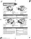
WARNING
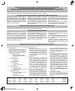
Debris Guard Linkage, Springs, Controls Muffler, Spark Arrester
CLEAN
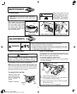
Daily or before every use, clean
grass, chaff or accumulated de-
bris from engine. Keep debris
guard clean. Keep linkage, spring
and controls clean. Keep area
around and behind muffler free of
any combustible debris.
CLEAN
CLEAN
CLEAN
CLEAN
CLEAN
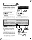
ADJUSTMENTS
WARNING
Prevent unintentional starting. Before performing adjustments:
• Remove spark plug wire from spark plug.
• Disconnect battery at negative terminal (only engines with electric start).
• ALWAYS de-energize starter, lock and remove safety key. (See section
To De-Energize Touch-N-Mow) Starter)
CARBURETOR ADJUSTMENT
WARNING
The manufacturer of the equipment on which this
engine is installed specifies top speed at which the
engine will be operated. DO NOT EXCEED this speed.
The carburetor on this engine is not adjustable.
Note: Engines operated at about 3000 to 5000 feet (900 to 1500
meters) above sea level may require a high altitude carburetor
main jet. If erratic performance is observed, contact a Briggs &
Stratton Authorized Service Dealer for cost to install/purchase a
high altitude carburetor main jet, if available.
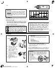
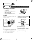
TO ADJUST STOP SWITCH
Governor control lever
should make good con-
tact with stop switch.
Check operation of
throttle.
Readjust if necessary.
GOVERNOR
CONTROL
LEVER
STOP
SWITCH
THROTTLE ADJUSTMENT
The governor lever on this engine is bent into position and is
not adjustable. See your authorized Briggs & Stratton
dealer or follow the instructions below.
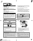
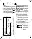
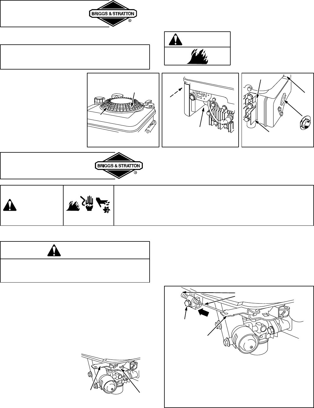
TO ADJUST REMOTE THROTTLE **
** On some models the governor lever is bent into position
and is not adjustable.
[1] Loosen casing clamp screw.
[2] Move governor control lever, wire, and casing as
far as possible in direction shown.
[3] Move remote throttle control to FAST and tighten
casing clamp screw.
[4] Move throttle to STOP (if equipped).
GOVERNOR
CONTROL
LEVER
CASING
CLAMP
SCREW
WIRE &
CASING