


15
Briggs & Stratton Power Products Home Generator
Owners Manual
Low Battery Voltage
This fault is indicated by one blink.This condition occurs if
the generator cannot start because the starting battery
output power is below that needed to crank the engine.
Causes for this problem may be a faulty battery or trickle
charger circuit.
To remedy the problem, contact your local service center
to check the battery trickle charge output. Remove the
15 Amp fuse and disconnect the battery from the generator.
Take the battery to a local battery store for analysis.
Replace the battery after it has been fully recharged,
connecting the NEGATIVE cable last. Install the 15 Amp fuse.
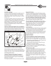
Low Oil Pressure
This fault is indicated by two blinks.The unit is equipped
with an oil pressure switch (Figure 4) using normally closed
contacts that are held open by engine oil pressure during
operation. Should oil pressure drop below the 8 psi range,
switch contacts close and the engine is shut down.
To remedy the low oil pressure condition, add the
recommended oil to the FULL mark on the dipstick.
If low oil pressure condition still exists, engine will start,
then shut down after about 10 seconds and diagnostic LED
will flash. In this case, contact an authorized service facility.
Low Voltage (Generator)
This fault is indicated by three blinks.This condition is
caused by a restriction in the fuel flow, a broken or
disconnected signal lead, a failed alternator winding, the
control panel circuit breaker is open, or Home Standby
Generator is overloaded.
To remedy the problem, contact your local service center.
Engine Fail To Start
This fault is indicated by four blinks.This feature prevents
the generator from damaging itself if it continually attempts
to start in spite of another problem, such as no fuel supply.
Each time the system is directed to start, the unit will crank
for 15 seconds, pause for 15 seconds, crank for 15 seconds,
pause for 15 seconds, and repeat. If the system does not
begin producing electricity after approximately 90 seconds,
the unit will stop cranking and the LED will blink.
The most likely cause of this problem is no fuel supply.
Check the inside and outside fuel shut off valves to ensure
they are fully open. Other causes could be failed spark
plug(s), failed engine ignition, or the engine air filter is
clogged.You may need to contact your installer for
assistance if you can’t remedy these problems.
Low Frequency
This fault is indicated by 5 blinks.This feature protects devices
connected to the transfer switch by shutting the generator
down if the engine runs slower than the preset limit.
This condition is caused by a failed engine governor or by
excessive loads on the generator.To remedy the problem,
you may need to contact your installer or local service
center for assistance.
Engine Overspeed
This fault is indicated by 6 blinks.This feature protects
devices connected to the transfer switch by shutting the
generator down if the engine happens to run faster than
the preset limit.The overspeed fault is detected as follows:
• If the generator output frequency runs at 72 Hz for five
seconds, the generator will shut down.
• If the generator output frequency reaches 75 Hz, the
generator will shut down instantly.
This condition is caused by a failed engine governor.To
remedy the problem, you should contact your installer or
local service center for assistance.
Oil Temperature High
This fault is indicated by seven blinks.The contacts of the
temperature switch (Figure 4) are normally open. If the
engine oil temperature exceeds approximately 140°C
(284°F), the fault is detected and the engine shuts down.
Common causes for this condition include running the unit
with all access doors removed, obstructed air inlet or
exhaust port, low oil level, or debris in the engine cylinder
cooling fins.
To resolve the problem, remove any accumulated debris and
obstructions and let the engine cool down. Ensure that the
Oil Service door and/or the Control Panel door is installed
whenever the unit is running.
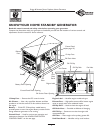
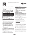
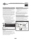
Figure 4 — Low Oil Pressure & High Temp. Switches
High
Temperature
Switch
Oil Drain
Fitting
Oil
Pressure
Switch