


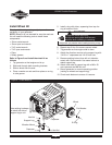
6200W Portable Generator
12
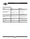
Stopping the Engine
1. Turn OFF and unplug all electrical loads from
generator panel receptacles. NEVER start or stop
engine with electrical devices plugged in and
turned ON.
2. Let engine run at no-load for several minutes to
stabilize internal temperatures of engine and
generator.
3. Turn engine off according to instructions given in
the engine operator’s manual.
4. Move fuel valve to “Off” position.
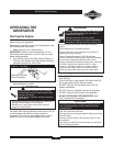
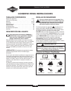
RECEPTACLES
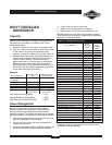
120/240 Volt AC, 30 Amp, Locking
Receptacle
Use a NEMA L14–30 plug with this receptacle.
Connect a 4–wire cord set rated for 250 Volt AC loads
at 30 Amps (or greater) (Figure 6). You can use the
same 4–wire cord if you plan to run a 120 Volt load.
This receptacle powers 120/240 Volt AC, 60 Hz, single
phase loads requiring up to 6,200 watts of power
(6.2 kW) at 25.8 Amps for 120 Volts or 240 Volts. The
outlet is protected by a push–to–reset circuit breaker.
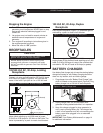
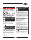
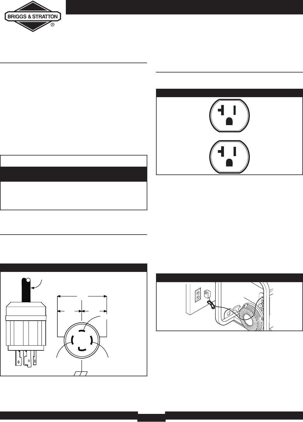
120 Volt AC, 20 Amp, Duplex
Receptacle
Each duplex receptacle (Figure 7) is protected against
overload by a push–to–reset circuit breaker.
Use each receptacle to operate 120 Volt AC,
single–phase, 60 Hz electrical loads requiring up to 2,400
watts (2.4 kW) at 20 Amps of current. Use cord sets that
are rated for 125 Volt AC loads at 20 Amps (or greater).
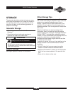
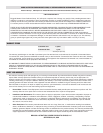
BATTERY CHARGER
Use battery float charger jack to keep the starting battery
charged and ready for use. Battery charging should be
done in a dry location, such as inside a garage.
1. Plug charger into unit’s “Battery Float Charger” jack,
which is located on the starter switch (Figure 8). Plug
battery charger into a 120 Volt AC wall receptacle.
2. Unplug charger from unit and wall outlet when
generator is being started and while it is in operation.
3. Keep this charger plugged in when generator is
not in use to prolong battery life. The charger has
a built in float equalizer and will not overcharge the
battery, even when plugged in for an extended
period of time.
IMPORTANT: See “Battery Maintenance” on page 14
for additional information.
Figure 7 — 120 Volt, 20 Amp Duplex Receptacle
Figure 6 — 120/240 Volt AC, 30 Amp Receptacle
4-Wire Cord Set
240V
120V
120V
W (Neutral)
X (Hot)
Y (Hot)
NEMA L14-30
Ground (Green)
• NEVER attempt to power a device requiring more
amperage than generator or receptacle can supply.
• DO NOT overload the generator. See “Don’t Overload
Generator”.
Receptacles may be marked with rating value
greater than generator output capacity.
CAUTION
Figure 8 — Battery Charger Jack