


7
ASSEMBLY
IMPORTANT: Read entire operator’s manual before you
attempt to assemble or operate your new pressure washer.
Unpack the Pressure Washer
1. Remove everything from carton except pressure
washer.
2. Open carton completely by cutting each corner from
top to bottom.
3. Remove pressure washer from carton.
Carton Contents
Items in the carton include:
• Main unit
• High pressure hose
• Handle
• Engine oil (2)
• Spray gun with quick connect fitting
• Nozzle extension with quick connect fitting
• Accessory bag (includes the following):
• Owner’s registration card
• Safety goggles
• Bag containing 5 multi–colored quick connect spray
tips
• Operator’s manual
• Engine operator’s manual
• Handle Fastening Hardware Kit (which includes):
• Carriage Bolts (2)
• Plastic Knobs (2)
If any of the above parts are missing or damaged, call the
pressure washer helpline at 1–800–743–4115.
PREPARING PRESSURE
WASHER FOR USE
If you have any problems with the assembly of your
pressure washer or if parts are missing or damaged, call the
pressure washer helpline at 1-800-743-4115.
To prepare your pressure washer for operation, you
will need to perform these tasks:
1. Fill out and send in registration card.
2. Remove and discard tape from domed oil filler cap on
top of pump.
3. Attach handle to main unit.
4. Add oil to engine.
5. Add fuel to fuel tank.
6. Connect high pressure hose to spray gun and pump.
7. Connect water supply to pump.
8. Connect nozzle extension to spray gun.
9. Select/attach quick connect spray tip to nozzle extension.
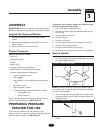
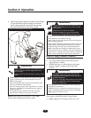
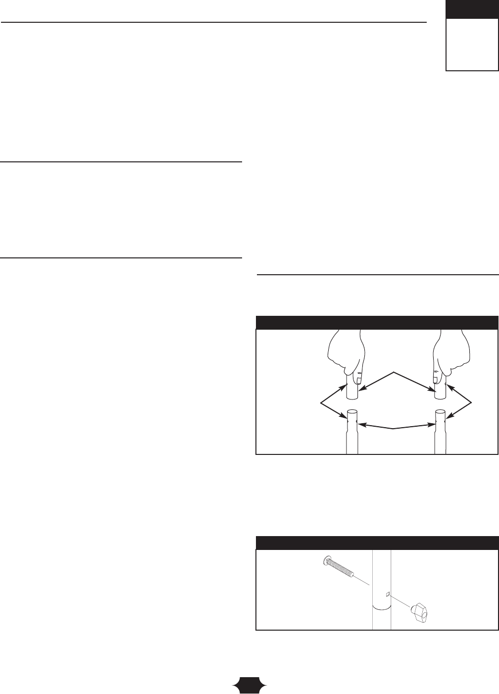
Attach Handle
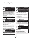
1. Place handle assembly onto handle supports connected
to main unit. Make sure holes in handle align with holes
on handle supports (Figure 1).
NOTE: It may be necessary to move the handle supports
from side to side in order to align the handle so it will slide
over the handle supports.
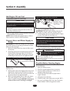
2. Insert carriage bolts through holes from outside of unit
and attach plastic knob on inside of handles (Figure 2).
Tighten by hand.
3. Insert multi–colored spray tips in spaces provided in
handle.
3
Section
Assembly
Figure 2 — Secure Handle
Align Holes
Handle
Handle
Supports
Figure 1 — Attach Handle to Base