


5
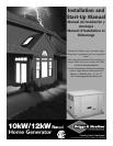
Briggs & Stratton Power Products Home Generator
Installation Manual
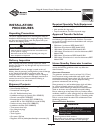
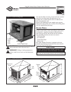
• Install the unit outdoors ONLY.
• Place the unit in a prepared location that is flat and has
provisions for water drainage.
• Install the unit where air inlet and outlet openings will
not become obstructed by leaves, grass, snow, etc. If
prevailing winds will cause blowing or drifting, you may
need to construct a windbreak to protect the unit.
• Install the generator as close as possible to the Transfer
Switch to reduce the length of wiring and conduit.
• Install the generator as close as possible to the fuel
supply to reduce length of pipes.
IMPORTANT: Laws or local codes may regulate the
distance to the fuel supply.
The Home Standby Generator is shipped already attached
to its mounting pad. Unless mandated by local code, a
concrete slab is not required.
If mandated by local code, construct a concrete slab at least
3 inches thick and 6 inches longer and wider than the unit.
Attach unit to slab with 1/4” diameter (minimum) masonry
anchor bolts long enough to retain the unit.
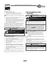
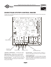
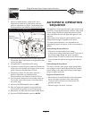
Fuel and Electrical Inlet Dimensions
Figure 2, below, depicts the location of the fuel piping
connector.Also shown is the recommended location for
punching holes for attaching the power conduit.
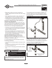
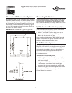
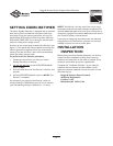
Lifting the Generator
The generator weighs more than 375 pounds. Proper tools,
equipment and qualified personnel should be used in all
phases of handling and moving the generator.
CAUTION! DO NOT lift unit by roof as damage to
generator will occur.
Two 48” lengths of 1” O.D. pipe (supplied by the installer)
are required to lift the generator manually. Insert pipes
through the lifting holes located near the unit’s base, as
shown in Figure 3 (next page).
Figure 2 — Generator Fuel and Conduit Attachment Locations, Oil Service Side of Unit
3/4” NPT
Fuel Piping
Connector
Recommended
Conduit Attachment
Area
4.5”
13.5”
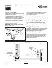
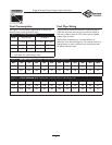
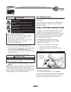
Figure 1 — Home Standby Generator Clearances
Exhaust
Port