


Getting Started Control Panel Guide
8 5
Before first using your power pack or after an extended storage period, it is recommended that the unit be
checked for basic operation as follows:
1. Remove the packaging and ensure that the unit is switched off.
2. Set up a flash head. Be sure the protective cap is removed and the modelling lamp is fitted and switched
on.
3. Plug the head into the socket of Channel A.
4. Set the Overall Power Selector to Symmetric/2400 and the Channel A Variator to Full.
5. Set the Modelling Mode Selector to Intermittent/Proportional.
6. Set Audio Switch to On, Photocell Switch to Off and Fast/Slow Switch to Slow.
7. Connect the power pack to a 230V AC, 50/60Hz outlet using the power cord.
8. Set the Power On/Off Switch to On. The unit will show “2400” on the Channel A display. The pack will now
charge to this setting.
9. Confirm after a few seconds that the Ready Indicator lights up, the Audio Ready Signal beeps and the
flash head’s Modelling Light is on at Full brightness.
10. Use the Test Button to discharge the set power into the head.
11. Confirm that the head flashes, the power pack recycles and Ready Indicator lights up.
12. Repeat steps 8 and 9 with the Overall Power Selector set to Symmetric/1200, Symmetric/600,
Asymmetric/1200, Asymmetric/600 and Asymmetric/300. Confirm that there is an appropriate change of
light output with each change of setting. Use a flash meter if possible.
13. Reduce the Channel A Variator setting to -3.0 and confirm that the Modelling Light has dimmed.
14. Confirm that the head flashes, the power pack recycles and Ready Indicator lights up.
15. Switch the power pack off. Plug the head into channel B.
16. Set the Overall Power Selector to Asymmetric/1200 and both Channel Variators to Full.
17. This time both numeric displays will show “1200.” The power pack will now charge to this setting.
18. Confirm after a few seconds that the Ready Indicator lights up, the Audio Ready Signal beeps, and the
flash head’s Modelling Light is on at Full brightness.
19. Use the Test Button to discharge the set power into the head.
20. Confirm that the head flashes, the power pack recycles and the Ready Indicator lights up.
21. Repeat steps 16 to 19 with the Overall Power Selector set to Asymmetric/600 and Asymmetric/300.
Confirm that there is an appropriate change of light output with each change of setting.
Use a flash meter if possible.
You are now ready to begin using the generator.
NOTES:
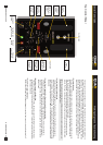
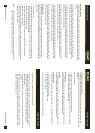
1 The QUAD2400 displays the power
available to each channel in watt-seconds on
the two red numeric Power Level Displays
marked Channel A and Channel B.
2 Beneath the Channel Power Level Displays
are the Channel Variators. These control the
individual power available from the Head
Sockets A and B in
1
/3 stop increments.
NOTE: The individual Channel Variators and
Power Level Displays are aligned with the
associated socket.
3 The Fast/Slow Switch, Overall Power
Selector and Modelling Mode Selector are
common to both channels.
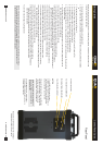
Rear Panel
AC Inlet 230VAC 50/60Hz 16A
Flash Thermal Reset Button
Power On/Off Switch
Modelling Thermal Reset Button
The AC Inlet, On/Off Switch and Thermal Reset
Buttons are mounted on the rear panel.
NOTE: If the unit has been left unused for six months or predominantly used with low power settings,
it is recommended that the Power Level be increased to Maximum and the unit left switched on for
at least 30 minutes occasionally to help preserve the life of the capacitors.
www.bowens.co.uk www.bowens.co.uk