


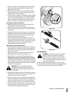
To adjust, disconnect ferrule from brake bracket assembly.
Thread ferrule in (towards idler) to increase tension on belt,
or out to decrease belt tension.
NOTE: The brake puck must always be firmly seated in the
pulley groove when auger control is disengaged.
IMPORTANT: Repeat the “Testing Auger Drive Control” from
the Assembly and Set-up section before operating the
snow thrower.
Drive Belt Replacement
If not already done, remove the auger drive belt from the
front pulley of the engine double pulley. Refer to “Auger
Belt Replacement” instructions in the previous sub-section.
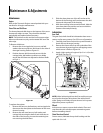
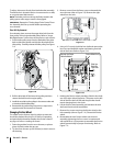
Pull the idler pulley away from the backside of the drive
belt to relieve the tension and slip the drive belt off the
idler pulley. Carefully release the idler pulley. See Figure
7-8.
Roll the drive belt off the lower drive pulley and then
remove the belt from the engine pulley.
Install the new belt on the pulleys in the reverse order and
re-tension with the idler pulley.
Reassemble by performing the previous steps in the
opposite order and manner of removal.
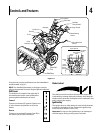
Changing Friction Wheel
The rubber on the friction wheel is subject to wear and
should be checked after the first 25 hours of operation,
and periodically thereafter. Replace the friction wheel if
any signs of wear or cracking are found.
Drain the gasoline from the snow thrower, or place a
piece of plastic under the gas cap.
Tip the snow thrower up and forward, so that it rests on
the housing.
1.
2.
3.
4.
1.
2.
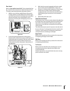
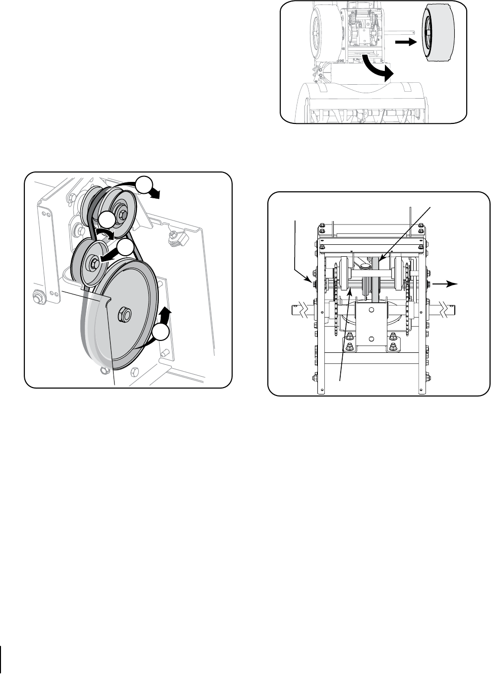
Remove screws from the frame cover underneath the
snow thrower (refer to Figure 7-9). Remove the right
wheel from the axle.
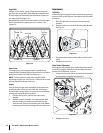
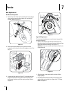
Using a 3/4” wrench, hold the hex shaft and remove the
hex screw and belleville washer and bearing from left
side of the frame. Refer to Figure 7-10.
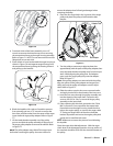
Holding the friction wheel assembly, slide the hex shaft
out of the right side of the frame. The spacer on the left
side of the hex shaft will fall and the sprocket should
remain hanging lose in the chain.
Lift the friction wheel assembly out between the axle
shaft and the drive shaft assemblies.
Remove four screws securing the friction wheel to the
hub assembly (refer to Figure 7-11). Discard old friction
wheel.
Reassemble the new friction wheel onto the hub
assembly, tightening the four screws in rotation and
with equal force. It is important to assemble the friction
wheel symmetrically for proper functioning. Refer to
Figure 7-11.
3.
4.
5.
6.
7.
8.
Figure 7-8
Figure 7-9
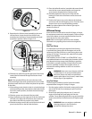
Figure 7-10
2
3
1a
1b
Friction Wheel Ass’y.
Hex Shaft
Slide Hex
Shaft Out
Right Side
Remove Hex Screw
Belleville Washer
20 sectiOn 7— service