


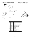
22
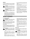
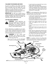
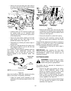
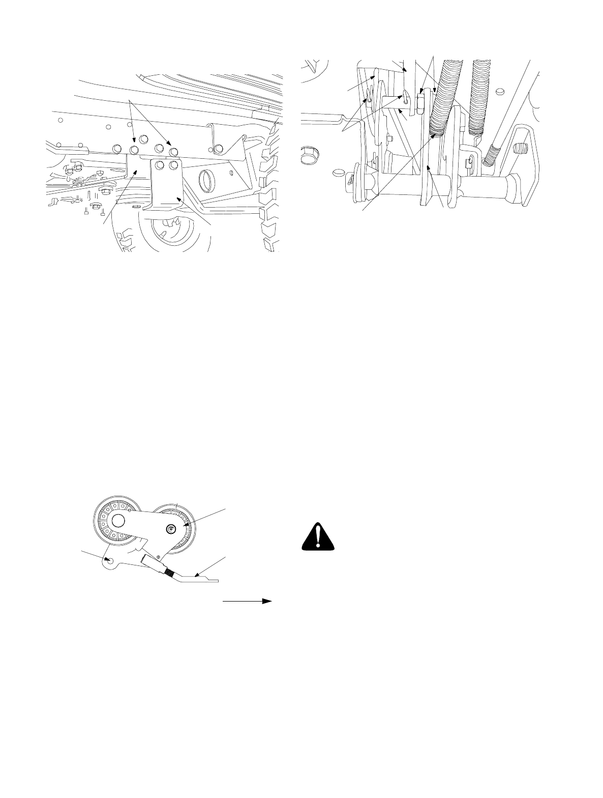
• Remove the two hex bolts (from both sides of
the tractor) that affix the PTO actuator bracket
to the tractor frame. See Figure 19.
Figure 19
• Carefully lower the PTO actuator bracket and
the engine pulley as an assembly while
removing the drive belt from the upper portion
of the engine pulley.
• Remove the drive belt by feeding it from both
ends toward the front idler pulley on the
double-idler bracket. See Figure 16.
• Reassemble by following the above steps in
reverse order.
• Reroute the new belt around the pulleys and
belt keepers EXACTLY as the old one was
routed. Refer to Figure 16.
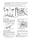
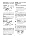
The AutoDrive
™
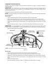
pedal is properly adjusted when the
hole found in the double-idler bracket has
approximately 1-3/8" of travel with ten pounds of
pressure applied to the AutoDrive
™
pedal. See
Figure 20.
Figure 20
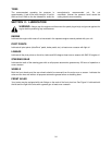
Adjust the AutoDrive
™
pedal after replacing the drive
belts on your tractor, if necessary, as follows:
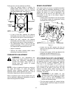
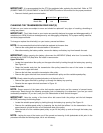
• Locate the speed control assembly on the
underside of the steering support bracket. See
Figure 21.
Figure 21
• Remove both hairpin clips from the pin which
is fastened to the speed control assembly (be
careful not to lose the small flat washers found
on the pin). See Figure 21.
• Remove the AutoDrive
™
pedal return spring.
• Using two 9/16" wrenches, remove the pin
from the speed control assembly. See Figure
21.
Thread the idler adjustment rod inward or outward to
lengthen or shorten the travel of the double-idler
bracket until proper adjustment is achieved.
• Reassemble by following the above steps in
reverse order.
IMPORTANT:
After replacing the drive belts,
perform the PTO adjustment as instructed in the
ADJUSTMENTS
section of this manual prior to
operating the tractor.
CUTTING BLADES
WARNING:
Cutting blades are sharp.
Always protect hands by wearing heavy
leather work gloves to grasp blades.
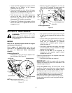
The blades may be removed for sharpening or
replacement as follows.
• Remove the deck from beneath the tractor,
(refer to DECK REMOVAL earlier in this
section for detailed instructions) then gently
flip the deck over to expose its underside.
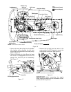
• Place a block of wood between the center
deck housing baffle and the cutting blade to
act as a stabilizer. See Figure 22.
• Use a 15/16" wrench to remove the hex flange
nut that secures the blade to the spindle
assembly. See Figure 22.
Hex Bolts
PTO Actuator
Bracket
Deck Stop
Front of Tractor
NOTE:
View shown from above tractor.
Double-idler
Bracket
Idler
Adj. Rod
Hole
Speed Control
Assembly
Hairpin
Clips
Idler
Adj. Rod
Pin
AutoDrive
™
Pedal
Return Spring
Place Wrenches Here
Neutral
Return
Bracket