


16
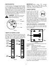
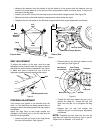
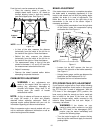
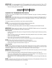
Front tire toe-in can be measured as follows:
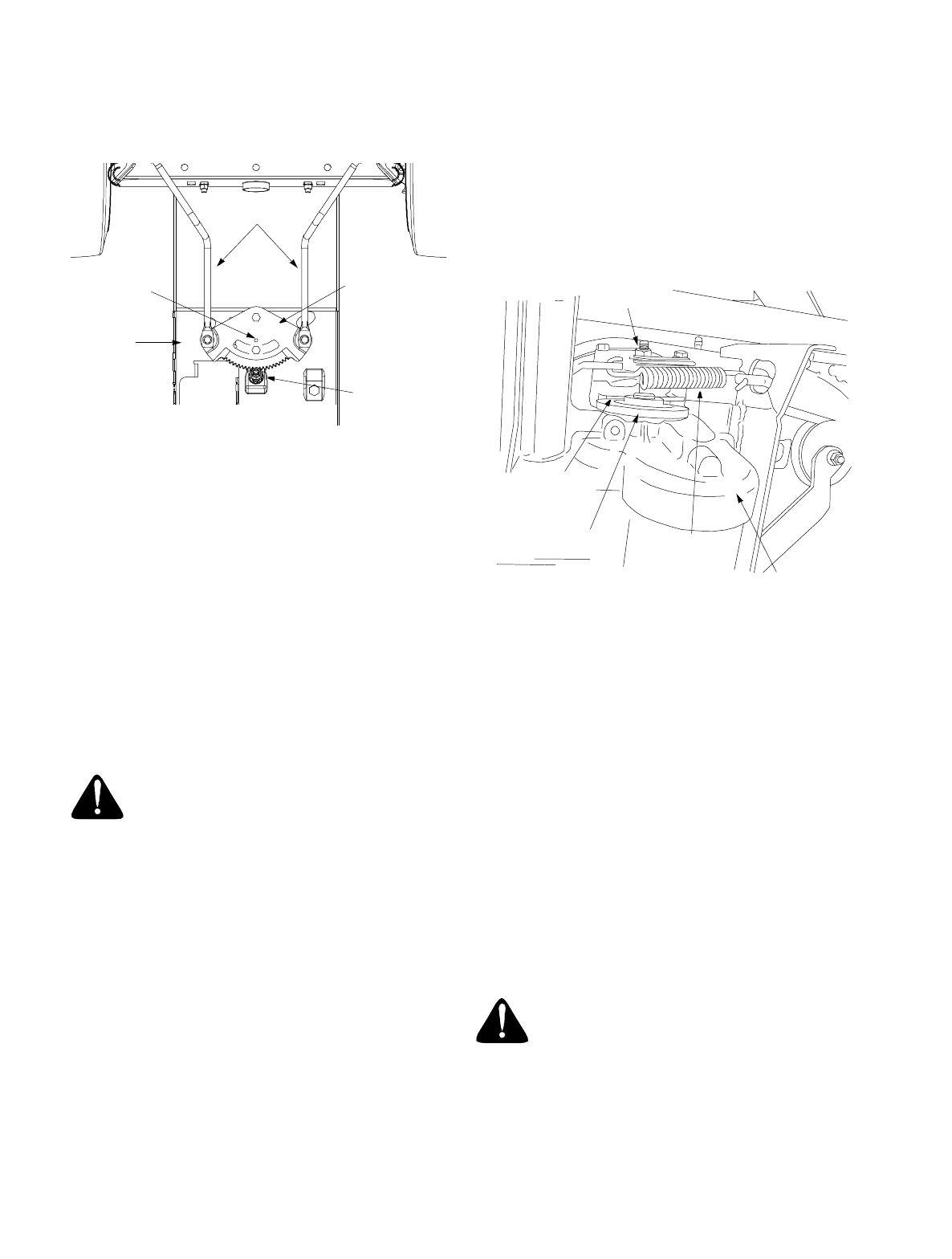
• Place the steering wheel in position for
straight ahead travel. Insert a 1/4" dowel up
through aligning holes in both the steering
gear and support plate. See Figure 10.
Figure 10
• In front of the axle, measure the distance
horizontally from the inside of the left rim to
the inside of the right rim. Note the distance.
• Behind the axle, measure the distance
horizontally from the inside of the left rim to
the inside of the right rim. Note the distance.
• The measurement taken in front of the axle
should be between 1/16" and 5/16" less than
the measurement taken behind the axle.
• Adjust if necessary.
• Remove the dowel inserted earlier before
attempting to operate the tractor.
CARBURETOR ADJUSTMENT
WARNING:
If any adjustments are
made to the engine while the engine is
running (e.g. carburetor), disengage all
clutches and blades. Keep clear of all
moving parts. Be careful of heated
surfaces and muffler.
NOTE:
A dirty air cleaner will cause an engine to
run rough. Be certain it is clean and properly
attached before adjusting carburetor. Refer to
separate engine manual packed with your unit for
information regarding air cleaner maintenance.
Refer to separate engine manual packed with your
unit for carburetor adjustment information or see an
authorized engine service dealer.
BRAKE ADJUSTMENT
If the tractor does not come to a complete stop when
the brake pedal is completely depressed, or if the
tractor’s rear wheels can roll with the parking brake
applied, the brake is in need of adjustment. The
brake disc can be found on the right side of the
transmission in the rear of the tractor. Adjust if
necessary as follows:
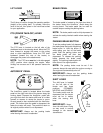
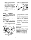
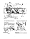
• Looking at the transmission from the right side
of the tractor, locate the compression spring
and brake disc. See Figure 11.
Figure 11
• Loosen, but do NOT remove, the hex nut
found on the right side of the brake assembly.
See Figure 11.
• Using a feeler gauge, set the gap between the
brake disc and the brake puck at .011".
• Re-tighten the hex nut loosened earlier.
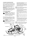
PTO (POWER TAKE-OFF) ADJUSTMENT
If your tractor’s engine fails to crank when following
the starting instructions found earlier in this manual,
the PTO may be in need of adjustment. With the
PTO lever in the disengaged (OFF) position, the
lever must go back far enough so that a metal tab
that is bolted to the base of the lever can fully
depress a plunger saftey switch mounted to the
tractor’s frame beneath the fuel tank. Adjust, if
necessary, as follows:
WARNING:
If the blades on your
tractor’s cutting deck continue to turn with
the PTO lever in the disengaged (OFF)
postion, stop the tractor immediately and
perform the following steps.
• Turn the tractor’s engine off, remove the key
from the ignition switch and apply the tractor’s
parking brake.
Steering Gear
Insert Dowel
Here
Drag Links
Steering
Shaft
Support
Plate
NOTE:
View shown from beneath tractor.
Brake Disc
Hex Nut
Compression
Spring
Set Gap
at .011"
NOTE:
View shown from beneath tractor.
Transmission