


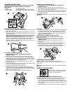
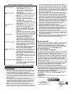


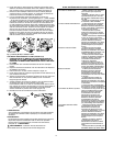
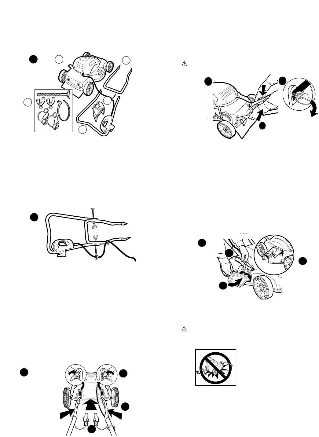
REMOVING THE HANDLE (FIGURE 4)
1. UNPLUG TOOL, AND WAIT FOR BLADE TO COME TO A
COMPLETE STOP.
2. Brace the rear of the mower so that it cannot roll backward.
3. Push down on each shroud hole cover tab, and rotate each shroud
hole cover out of the shroud. (Figure 4A)
4. Grasp the ends of the lower handle with both hands. Squeeze the
two sides of the handle towards one another while pulling back on
the handle. (Figure 4B)
WARNING: NEVER use a sharp object to move jacketed wires out
of the way.
MULCHING
The mower is designed to mulch or discharge the grass depending
on whether mulch door is closed (mulching) or the mulch door is
up and the discharge chute is in place (discharging). No further
assembly steps are required if you are mulching. PROCEED TO
OPERATING INSTRUCTIONS.
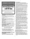
DISCHARGE CHUTE INSTALLATION (FIGURE 5)
(If you wish to discharge the clippings rather than mulch,
perform these steps)
1. UNPLUG TOOL, AND WAIT FOR BLADE TO COME TO A
COMPLETE STOP.
2. Open mulch door by pulling on the mulch door finger grip.
(Figure 5A)
3. Align the discharge chute arrows with the positioning arrows on
the mower deck and insert the discharge chute as shown.
4. Position the chute until the chute hooks are trapped under the
deck hooks and release the chute and door. (Figure 5B)
OPERATING INSTRUCTIONS
NOTE: A mower is a major appliance and should not be
operated simultaneously with other major appliances on the same
house circuit.
Warning: Make sure that other persons and pets are at least 100
feet away.
Remove all rocks, sticks, wire, toys, bones,
and other debris or items which might be
thrown by the rotating blades.
ATTACHING EXTENSION CORD TO MOWER (FIGURE 6)
DO NOT connect the extension cord to power source until you have
finished reading this manual and you are ready to start mowing.
1. The extension cord must be polarized and will only plug in one
way, orient the wide slot with the wide blade in the switch housing.
2. Loop the extension cord and push the loop up through the hole in the
switch housing.
3. Pull the extension cord on the side of the loop that is plugged into
INSPECT CUTTING AREA
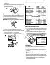
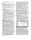
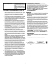
ASSEMBLY INSTRUCTIONS
BEFORE ASSEMBLING YOUR MOWER, CHECK THAT YOU HAVE
RECEIVED THE FOLLOWING IN THE SHIPPING CARTON.
SEE FIGURE 1.
A. Mower D. Discharge Chute
B. Upper Handle E. Plastic Bag with handle bolt, 2 wing nuts,
C. Lower Handle 2 star washers, cable tie and 2 shroud hole covers
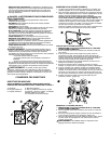
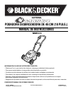
ASSEMBLING THE HANDLE (FIGURE 2)
1. Your mower carton contains the mower, 2 handles, discharge chute
and 1 plastic parts bag.
2. Fasten the upper and lower handle halves together using the eye
bolt (already installed on the power cord) and the bolt and wing nuts
from the plastic bag.
Make sure the power cord and switch are on the same side of
the mower as the discharge area. There are three holes on the
upper handle, this allows the handle height to be set in three
positions. Choose the hole that best suits your overall height. The
eye bolt is installed so that the cord is routed to the outside.
Place star washers on the bolts between handle and the wing nuts.
Tighten the wing nuts securely.
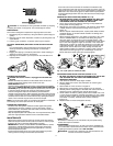
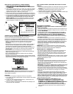
ATTACHING THE HANDLE (FIGURE 3)
1. UNPLUG TOOL, AND WAIT FOR BLADE TO COME TO A
COMPLETE STOP.
2. Brace the front end of the mower so that it cannot roll forward.
3. If shroud hole covers are joined, remove connector and discard it.
Slide each shroud hole cover retaining loop over an end of the han-
dle. Ensure that the arrows on the shroud hole covers are pointing
towards each other when installed. (Figure 3A)
4. Align the ends of the lower handle with the holes in the mower
shroud. (Figure 3B)
5. Push the handles into the mower until they are fully engaged taking
care not to pinch or damage the power cord.
6. Pull back on the handles to ensure a secure fit.
7. Install shroud hole covers by inserting the bottom edge of the
shroud hole cover onto the bottom edge of the shroud hole, then
rotate hole cover forward and push down until it is firmly snapped into
position in the shroud. (Figure 3C)
8. Install cable tie on lower handle to secure cord. (Figure 5C)
3
C
B
A
2
5
A
B
4
A
B
4
C
1
D
C
A
B
E