ASSEMBLY FOR BLOW MODE
WARNING: Before attempting any of the assembly steps below, ensure product is switched off and
disconnected from the power supply.
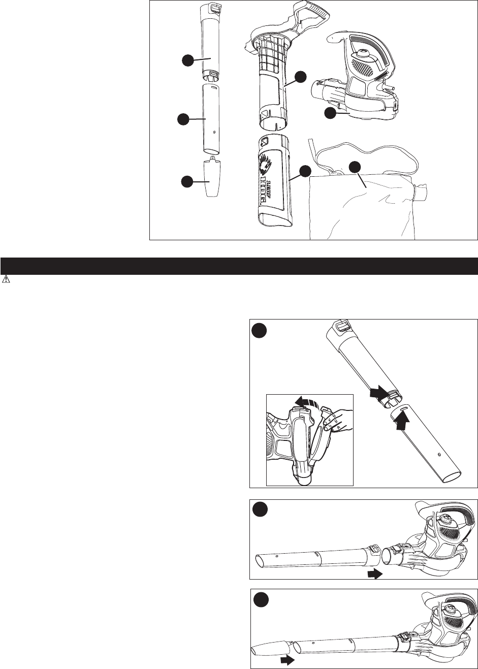
BLOW TUBE ASSEMBLY (FIGURES 1-3)
• Ensure grill cover is attached to the power head. If not,
attach cover as shown in the inset of figure 1. NOTE: Unit
will not operate in blow mode without grill cover in place.
Align the upper and lower tubes as shown in figure 1.
• Push the lower tube firmly into the upper tube, until the
tubes click into place.
• Blow tubes must be assembled to the power head before
use.
• Never operate without both lower and upper tubes
assembled.
• In the interest of safety, it is not intended for the tubes to be
separated once assembled.
• Push the tube assembly onto the power head until it is in the
fully locked position (figure 2).
• Use the air concentrator attachment to target air flow to a
tighter area. Add the attachment to the assembly as shown
in figure 3. Push on until hole in tab engages raised post on
tube.
4
Functional Description
a. Power head
b. Upper blow tube
c. Lower blow tube
d. Concentrator
e. Upper vac tube
f. Lower vac tube
g. Shoulder bag
a
g
b
e
c
d
f
3
2
1


