


SAVE THESE INSTRUCTIONS
ASSEMBLY / ADJUSTMENT SET-UP
ASSEMBLY TOOLS REQUIRED (NOT SUPPLIED):
- Phillips Screwdriver
ATTACHING THE TWO PIECE GUARD
WARNING: UNPLUG THE TOOL BEFORE ATTEMPTING TO ATTACH THE GUARD.
NEVER OPERATE TOOL WITHOUT GUARD FIRMLY IN PLACE. THE GUARD MUST
ALWAYS BE ON THE TOOL TO PROTECT THE USER.
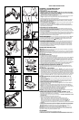
• Remove the two guard sections from the carton.
• Attach the first guard section with side tab into the groove around the housing as shown
in figure 1. Align the hole in the guard with the post on the trimmer housing.
• Remove the screw from the second guard section.
• Insert the top tab from the second guard section into the first guard section as shown in
figure 2. NOTE: The rib behind the tab should be hooked over the rib of the first
guard section. (See inset figure 2).
• Insert the side tab from the first guard section into the slot of the second guard section until
you hear them “snap” together (figure 3).
• Insert the
3
/4
inch (19mm) screw as shown in figure 4 to complete the guard assembly.
• Once the guard is installed, remove the covering from the line cut-off blade, located on the
edge of the second guard section.
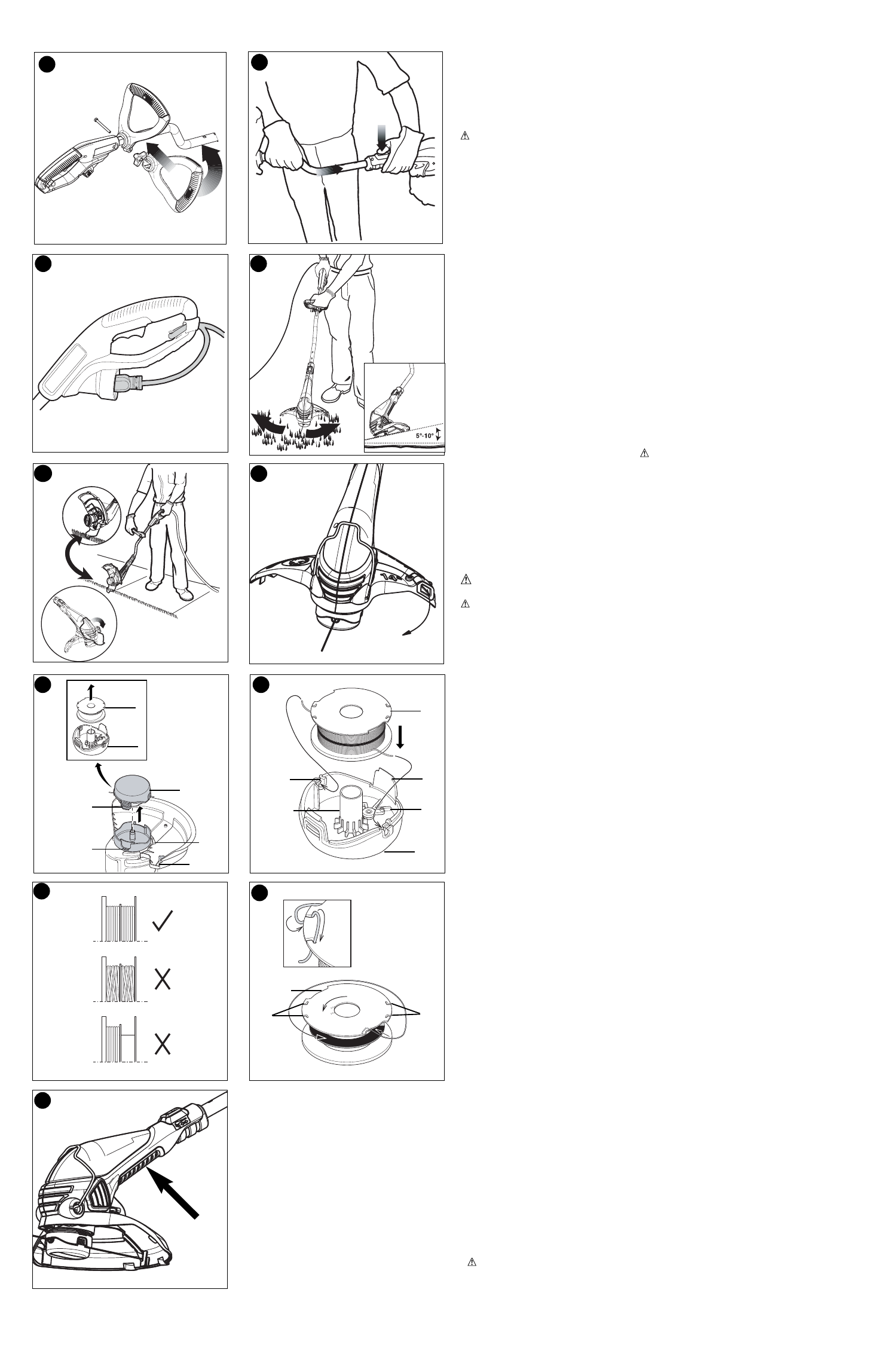
ATTACHING THE AUXILIARY HANDLE
• Attach the handle to the metal shaft of the trimmer (with the Black & Decker logo facing
upward) by pushing it onto the shaft from the side. Once it is pushed onto the metal shaft,
the handle can be turned into the correct orientation .
• Insert the 2-1/2 inch (63.5mm) bolt through the holes in the handle and thread on the plastic
knob as shown in figure 5.
• For maximum comfort and control, adjust the auxiliary handle to suit your height. Shorter
users adjust handle to a lower position (away from you) and taller users, adjust handle to an
upper position (towards you). The handle should be adjusted so that your front arm is
straight when the trimmer is in the working position.
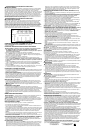
HEIGHT ADJUSTMENT
• The overall height of the trimmer can be adjusted by pressing the button shown in figure 6
and moving the metal tube up or down into one of the three rectangular recesses in the
tube until you hear it “snap” into place. CAUTION: Confirm that the tube is locked in
place by releasing the button and pushing down on the tube.
ATTACHING EXTENSION CORD
• An extension cord retainer (figure 7) is built into the switch handle that prevents the cord
from coming unplugged. To use this feature, simply double the extension cord about 8
inches (203mm) from the end, and insert it into the slot in the bottom of the handle area.
Hook the loop formed by doubling the cord over the tab. Gently tug on the cord to insure
that it is firmly retained in the trimmer’s handle. Plug the receptacle end of the extension
cord into the plug blades in the trimmer.
OPERATING INSTRUCTIONS
WARNING:
Always use proper eye protection that conforms to ANSI Z87.1 (CAN/CSA
Z94.3) while operating this power tool.
CAUTION: Inspect area to be trimmed and remove any wire, cord, or string-like objects
which could become entangled in the rotating line or spool. Be particularly careful to avoid any
wire which might be bent outwardly into the path of the tool, such as barbs at the base of a
chain link fence.
SWITCHING ON AND OFF
• To switch the tool on, squeeze the trigger lever.
• To switch the tool off, release the trigger lever.
• With the unit on, angle unit and slowly swing the trimmer side to side as shown in figure 8.
• To operate as a maintenance edger, unplug the unit from the power source. Push the
button and rotate the tube 180° as shown in figure 6. The tool will lock in position. Gently
pull the wire edge guide down into place as shown in figure 9 and position the trimmer
above the surface as shown in figure 9.
• Return to the trimming position by unplugging the unit from the power source, pushing the
button and rotating the tube back 180°. The tool will lock in the trimmer position. When
using the tool return the wire edge guide to the original position, out of the way.
BLOWER FUNCTION (GH750 ONLY- FIGURE 10)
The GH750 funnels the air created by the motor up through the guard creating a built-in
sweeper. This feature can be used to blow grass clippings off of sidewalks and other hard
surface areas.
CUTTING LINE / LINE FEEDING
Your trimmer uses .065 inch (1.65 mm) diameter, ROUND nylon line. During use, the tips
of the nylon lines will become frayed and worn and the special self feeding line hub will
automatically feed and trim a fresh length of line. Cutting line will wear faster and require
more feeding if the cutting or edging is done along sidewalks or other abrasive surfaces
or heavier weeds are being cut. The advanced automatic line feeding mechanism senses
when more cutting line is needed and feeds and trims the correct length of line whenever
it’s required. DO NOT BUMP unit on ground in attempt to feed line or for any other pur-
poses.
FITTING A NEW SPOOL OF AFS CUTTING LINE (FIGURES 11 & 12)
• Unplug the tool.
• Depress the tabs (a) and remove the cassette (b) from the cassette housing (c) in the
trimmer head (figure 11).
• Grasp empty spool (d) with one hand and cassette with other hand and pull spool out
from cassette. If lever (e) in base of cassette becomes dislodged, replace in correct
position before inserting new spool into cassette.
• Remove any dirt and grass from the cassette and housing.
• Take the new spool and push it onto the boss (f) (figure 12) in the cassette. Rotate the
spool slightly until it is seated.
• Unfasten the end of one of the cutting lines and guide the line into one of the eyelets (g).
figure 12. The line should protrude approximately 4-3/8 inches (111mm) from the cassette.
• Unfasten the end of the other cutting line and guide the line into the other eyelet. The line
should protrude approximately 4-3/8 inches (111mm) from the cassette.
• Align the cassette tabs (a) with the slots (h) in the housing (figure 11).
• Push the cassette onto the housing until it snaps securely into place.
CAUTION: To avoid tool damage, If the cutting lines protrude beyond the trimming blade
(i), cut them off so that they just reach the blade (figure 11).
WINDING NEW LINE ONTO AN EMPTY SPOOL (FIGURES 13 &14)
You may wind new cutting line onto an empty spool. Replacement packs of .065 inch (1.65
mm) cutting line are available from your local dealer.
• Remove the empty spool from the tool as described in “FITTING A NEW SPOOL OF AFS
CUTTING LINE”.
• Remove any remaining cutting line from the spool.
• First wind new line onto the uppermost part of the spool.
- Feed 3/4 inch (19mm) of cutting line into one of the line anchoring slots.
- Wind the cutting line onto the spool in the direction of the arrow on the spool.
Make sure to wind the line on neatly and in layers. Do not crisscross (figure 13).
- When the wound cutting line reaches the recesses (j), cut the line. (figure 14).
- Temporarily park the line in the holding slots (k) on one side of the spool as shown in the inset
in figure 14.
• Repeat the above procedure for the second cutting line on the lower section of the spool.
• Fit the spool onto the tool as described in “FITTING A NEW SPOOL OF CUTTING LINE”.
CAUTION: Before you begin trimming, only use the appropriate type of cutting line.
Ensure that cutting line is present in both sections of the spool (figure 12).
IMPORTANT: To assure product SAFETY and RELIABILITY, repairs, maintenance and
adjustment should be performed by authorized service centers or other qualified service
organizations, always using identical replacement parts.
ACCESSORIES
Use Black & Decker replacement spool Model No. DF-065.
Reload nylon line (either bulk or prewound replacement spool) as shown in this manual.
• USE ONLY .065 inch (1.65 mm) DIAMETER NYLON MONOFILAMENT LINE. Do not use
10
9
7
8
11 12
13
14
h
j
k
g
f
i
a
a
d
c
b
d
k
b
b
e
6
5
15