


6
Under some conditions and duration of use, noise from this product
may contribute to hearing loss.
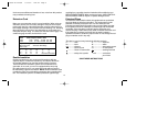
Extension Cord
Make sure your extension cord is in good condition. When using an
extension cord be sure it is heavy enough to carry the current your
product will draw. An undersized extension cord will cause a drop in
line voltage resulting in loss of power and overheating. The following
table shows the correct size to use depending on cord length and
nameplate ampere rating. If in doubt, use the next heavier gage. The
smaller the gage number, the heavier the cord.
Double Insulation
Double insulated tools are constructed throughout with two
separate layers of electrical insulation or one double thickness
of insulation between you and the toolÅfs electrical system.
Tools built with this insulation system are not intended to be
grounded. As a result, your tool is equipped with a two prong
plug which permits you to use extension cords without concern
for maintaining a ground connection. NOTE: Double insulation does
not take the place of normal safety precautions when operating this
tool. The insulation system is for added protection against injury
resulting from a possible electrical insulation failure within the tool.
REPLACEMENT PARTS: When servicing all tools, USE IDENTICAL
REPLACEMENT PARTS. Repair or replace damaged cords.
Polarized Plugs
To reduce the risk of electric shock, this equipment has a polarized
plug (one blade is wider than the other). This equipment must be
used with a suitable polarized 2 wire or 3 wire extension cord.
Polarized connections will fit together only one way. Make sure that
the receptacle end of the extension cord has large and small blade
slot widths. If the plug does not fit fully into the extension cord,
reverse the plug. If it still does not fit, obtain a suitable extension cord.
If the extension cord does not fit fully into the outlet, contact a
qualified electrician to install the proper outlet. Do not change the tool
plug or extension cord in any way.
The label on your tool may include the following symbols.
V................volts A ....................amperes
Hz..............hertz W ..................watts
min ............minutes ..................alternating current
..........direct current
n
o ..................no load speed
..............
Class II Construction
....................earthing terminal
............safety alert symbol .../min ............revolutions
per minute
SAVE THESE INSTRUCTIONS
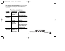
Minimum Gage for Cord Sets
Volts Total Length of Cord in Feet
120V 0-25 26-50 51-100 101-150
240V 0-50 51-100 101-200 201-300
Ampere Rating
More Not more American Wire Gage
Than Than
0-6 18 16 16 14
6 - 10 18 16 14 12
10 - 12 16 16 14 12
12 - 16 14 12 Not Recommended
479970-00 LP1000 9/14/05 1:00 PM Page 6