Part No. 520141 Form No. F061604A
Never store engine indoors or in enclosed poorly
ventilated areas with fuel in tank, where fuel fumes
may reach an open fl ame, spark or pilot light, as on a
furnace, water heater, clothes dryer or other gas appliance.
If engine is to be unused for 30 days or more, prepare
as follows:
Be sure engine is cool. Do not smoke. Remove all
gasoline from carburetor and fuel tank to prevent gum
deposits from forming on these parts and causing possible
malfunction of engine. Drain fuel outdoors, into an approved
container, away from open fl ame. Run engine until fuel tank
is empty and engine runs out of gasoline.
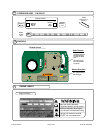
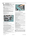
Using two people to lift machine is recommended. Lift holding the
handle and front of deck. Secure in place during transport.
NOTE: Fuel stabilizer (such as Sta-Bil) is an acceptable
alternative in minimizing the formation of fuel gum deposits
during storage. Add stabilizer to gasoline in fuel tank or
storage container. Always follow mix ratio found on stabilizer
container. Run engine at least 10 min. after adding stabilizer
to allow it to reach the carburetor.
CAUTION: Wheels must be chocked or blocked
when unit is parked on a slope.
HANDLING & TRANSPORTING:
16.7
STORAGE
16.8
16.6
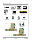
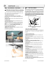
HILLSIDE MOWING
HILL
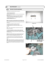
WARNING! Never mow on any slope greater than 15 degrees.
Always mow across the face of slopes; never up and down or
diagonally (see fi gure 16-8). DO NOT attempt sudden starts or stop
when mowing on a slope. Avoid sudden turns and use extreme caution
when changing direction on a slope.
Figure 16-8
Page 9 of 20
GROUND SPEED can be varied by selecting a higher or
lower gear using the gear shift lever on top of the console
(see figure 16-7). Under most conditions cutting should
be done in second or third gear. Fourth gear should be
reserved for conditions where grass is thinned out or not
as tall. The quality of the cut produced is directly related
to the unit's ground speed during cutting. If the quality of
the cut is not satisfactory (i.e. material left standing), you
should shift into a lower gear during cutting. For improved
control in confi ned areas, this machine can be pushed
forward or backward by releasing the drive lever located
at the bottom of the operator's right-hand handle while
depressing the brake release lever.
Figure 16-7
16.5
PROPULSION
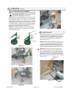
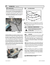
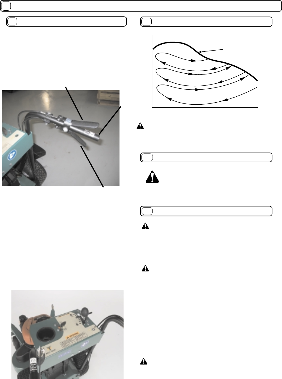
This unit is self-propelled, and is controlled by an
operator presence control. To engage the wheel drive,
first push down on the BRAKE RELEASE lever on
the right side, then lift the operator's DRIVE lever on
the right side against operator's handle. The drive is
disengaged by releasing the lower lever. (see fi gure
16-6). Push and hold the Brake lever to free wheel.
Fig. 2
Figure 16-6
drive lever -
up to drive
brake release lever
- down to release
operator's
handle
16
OPERATION continued
CAUTION: ENGINE MUST BE OFF while
handling, lifting, or transporting the unit on
or off the vehicle.


