Part No 430316 Form No F062006C
9
QB554HC Owner’s Manual
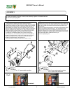
ASSEMBLY
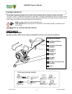
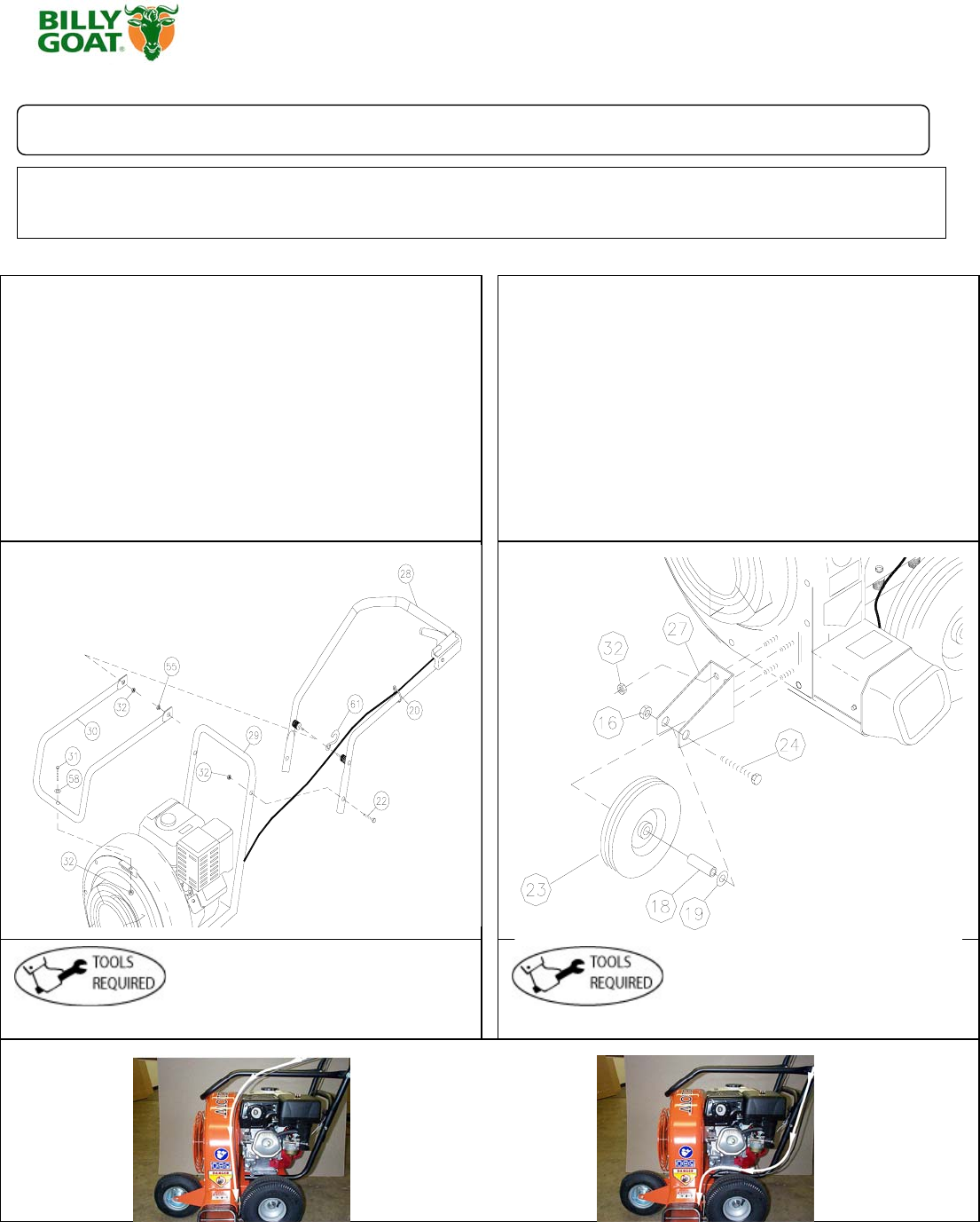
Figure A Figure B
Fig 2.
Incorrect Correct
1.Follow the steps in figures A and B, then securely tighten all hardware shown.
2.Connect spark plug wire.
1. The hardware for attaching the upper handle to the lower is
preinstalled in the proper location in the lower handle. Before the upper
handle can be installed you must remove the hardware from the handle
and reuse it in the same locations. Install upper handle (Item 28), to
preassembled lower handle (item 29) by sliding the upper over and
down the outside of the lower handle. Pull recoil handle from the engine
and place it between rope guides (Item 13). Using screw & lock nut to
install upper handle to lower handle. Finish installing the other side of
the upper handle assembly using screw and lock nut provided.
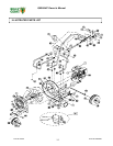
2. Install front of handle brace (Item 30), to blower housing using
one screw(Item 31), one washer (Item 58) and one lock nut (item 32)
located in the hardware bag. Install rear of handle brace (item 30) to
upper handle vibration mounts using two lock nuts (item 32) also
located in the hardware bag. Hand tighten only.
3. Securely tighten all hardware listed above in steps 1 thru 2.
4. Remove four lock nuts from the front plate and use them to attach the
front wheel bracket (Item 27). Using spacer (Item 18), washer (Item 19),
and Lock Nut (Item 16) to attach Front wheel (Item 23) onto the front
wheel bracket.
NOTE: Front wheel bracket (Item 27) should be mounted with the offset
portion of the bracket toward the ground. This will place the blower
exhaust parallel to the ground. The bracket can be mounted in the
opposite configuration to move the blower exhaust closer to the ground.
5. When ty-wrapping the diverter cable in place please be sure to follow
the correct routing of the cable as shown in Fig. 2.
6. Connect spark plug wire.
Two ½” open ended wrenches
One ½ open-end wrench and two
9/16” open-ended wrenches


