Part No 350245 Form No F062206A
9
CR Owner’s Manual
OPERATION
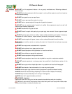
Like all mechanical tools, reasonable care must be used when operating machine.
Inspect machine work area and machine before operating. Make sure that all operators of t his
equipment are trained in general machine use and safety.
PUT OIL IN EN GINE BEFORE STARTING
STARTING
ENGINE: See engine manufacturer’s instructions for type and amount of oil and gasoline used. Engine must be
level when checking and filling oil and gasoline.
FUEL VA LVE: Move fuel valve to "ON" position (when provided on engine).
STOP SWITCH: Located on the engine. "slow/stop" position.
CHOKE: Operated with choke lever on side of engine.
THROTTLE: Controlled by throttle lever on the motor.
IF YOUR UNIT FAILS TO START:
See Troubleshooting on page 12.
HANDLING & TRANSPORTING:
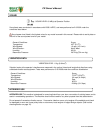
This unit requires two people to lift it. With the handle in the folded position, lift holding the lower handle and
belt/shaft guard one on each side of the machine. Secure the machine in place during transport. See page 3 for
weight specifications
Never lift the machine while the engine is running.
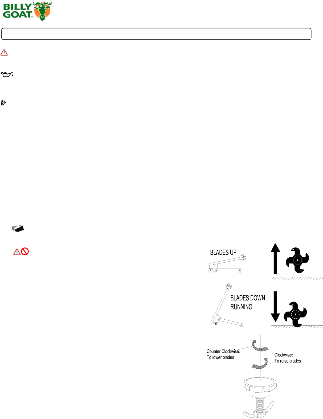
ADJUSTING BLADE DEPTH
The de
p
th of the blades can be raised or lowered b
y
rotatin
g
the knob on
the top of the adjustment lever. The blades are lowered by rotating the
knob counter-clockwise, and raised by rotating the knob clockwise. The
relative depth of the blades can be gauged by using the depth scale
located on the right front corner of the engine base.
FOLDING HANDLE
This unit is equipped with a folding upper handle for easier storage and transportation. The handle can be folded by
sliding the handle lock loops (item 28) up. Th is releases the upper handle, allowing it to be folded over the unit.
BLADE POSITION & DEPTH CONTROL LEVER
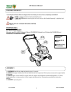
The blades can be raised or lowered into the ground by height adjustment
lever on the engine base. The resulting blade depth can be adjusted higher
or lower. See ADJUSTING BLADE DE PTH.


