


Part No. 890394 Form No. F011398B
Page 8 of 12
MAINTENANCE
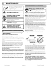
CHIPPER BLADE REMOVAL AND SHARPENING
Depending on the type and amount of wood being chipped, the
chipper blade will eventually get dull, losing it’s cutting ability.
Evidence of a dull blade is a noticeably reduced chipping ability or a
rough cut on end of branch.
Note: The chipper blade gap is factory set and should be checked
each time impeller is removed from engine crankshaft and reset if
required. If reassembly requires a different quantity of shim
washers, Billy Goat
® shim washer must be used.
Chipper blades are normal replaceable wear items.
DANGER Chipper blade is sharp.
Replace any damaged blade.
10. Using a 3/16" Allen wrench and 1/2" open end wrench, remove
chipper blade from impeller.
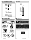
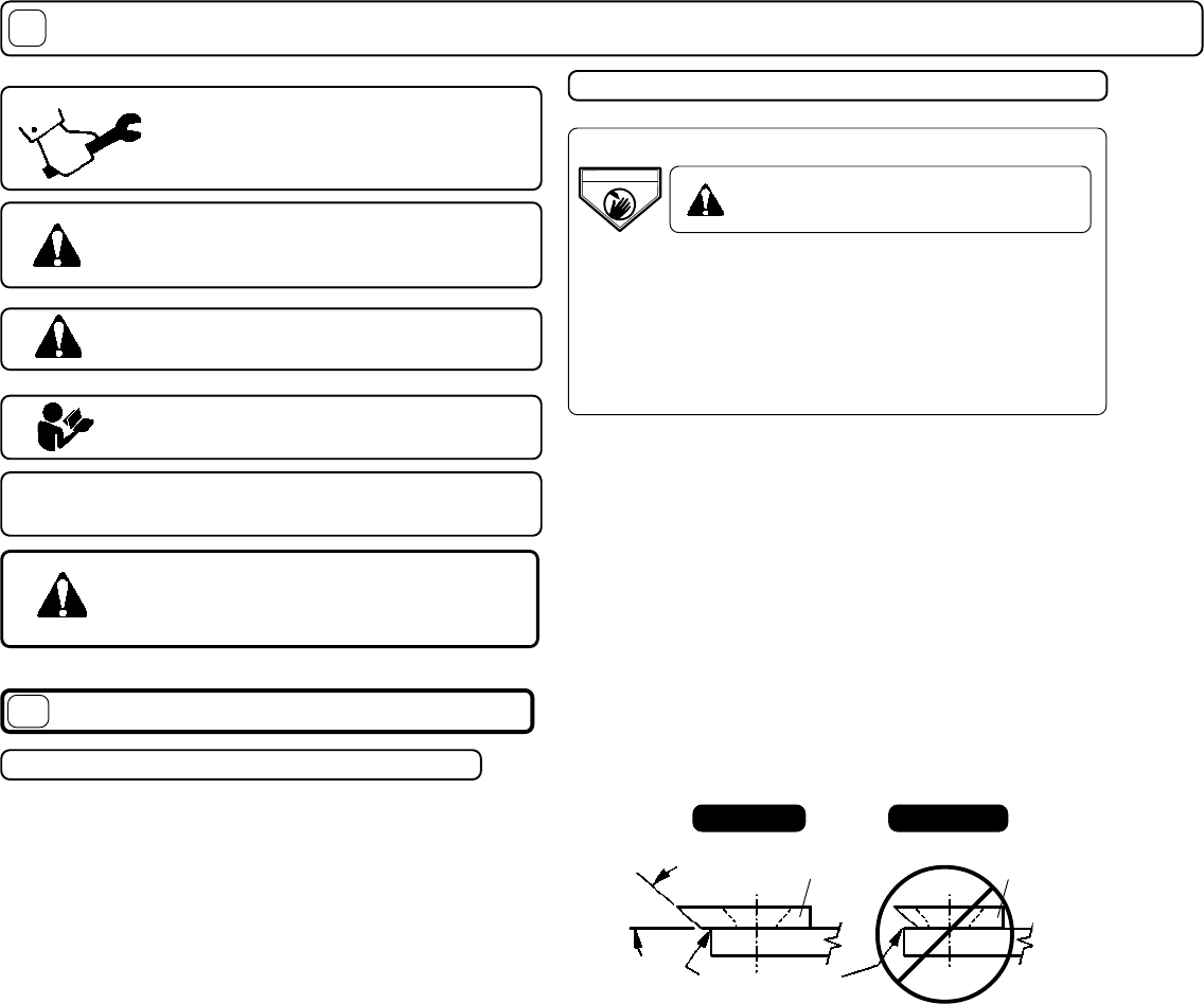
11. Sharpen blade by lightly grinding the cutting edge of the blade at
40 degrees (see fig. 5). It is not necessary to remove all nicks from
the cutting edge.
CAUTION:
Be careful to avoid heat buildup in the
blade during sharpening. This will reduce it’s heat- treated hardness
properties and will reduce blade life. Evidence of too much heat build-
up is a change of color along sharpened edge.
12. The same chipper blade can be sharpened several times.
However, blade replacement is required when blade no longer
overhangs the chip relief hole in impeller back plate or if increased
vibration occurs (see fig. 5).
13. Chipper blade installation is in reverse order of removal.
40
o
Blade
Blade
INCORRECTCORRECT
14. To reinstall impeller, use a new impeller bolt and lockwasher and
use exactly the same crankshaft impeller shim washers as were
removed during disassembly (unless they were damaged). Note:
your unit may or may not have required the use of shim washers
.
15. Tighten impeller bolt. Torque impeller bolt to 50 Ft. Lbs. (68 N
.
m)
(see item 51 on page 11).
16. Slowly rotate impeller to insure proper chipper blade clearance.
Check to see that gap between chipper blade and anvil surface (on
lower side of housing top plate) measures between 0.040"(1.02mm)
and 0.080"(2.03mm).
17. If gap is less than 0.040"(0.51mm), add shim washer 890130
(0.060"{1.52mm} thick) and/or 890131 (0.020"{1.02mm} thick),
whichever is required. If gap is more than 0.080"(2.03mm), remove
one or more shim washers as needed to obtain correct gap (see fig. 6
& fig. 7). The chipper will function at up to a maximum of
0.125"(3.18mm) gap.
EDGE OF CHIP
RELIEF HOLE
Fig. 5
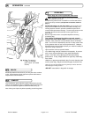
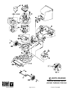
IMPELLER REMOVAL and CHIPPER ADJUSTMENT
1. Wait for engine to cool and disconnect spark plug.
2. Drain fuel and oil from the engine.
3. Remove bag, quick release, and upper handle. Do not kink, stretch,
or break control cables, control housings, or end fittings while removing
handles.
4. Remove housing top plate by removing bolts around outside of
housing.
5. Leaving engine fastened to top plate, remove impeller bolt and lock
washer and slide impeller off crankshaft ( A puller may be required).
6. Retain shim washers used at end of crankshaft for use at impeller
reinstallation (see fig. 7). However, your unit may or may not have
required the use of shim washers.
7. If impeller slides off freely, proceed to (step 11 or step 15).
(Do not drop impeller).
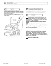
8. If impeller does not slide off crankshaft, place two crowbars between
impeller and housing on opposite sides. Pry impeller away from engine
until it loosens.
Using a penetrating oil can help loosen a stuck impeller.
9. If the impeller cannot be loosened, obtain a 1” (25.4mm) longer bolt of
the same diameter and thread type as the impeller bolt. Invert engine
and impeller and support engine above ground to prevent recoil
damage. Thread longer bolt by hand into the crankshaft until bolt
bottoms. Using a suitable gear or wheel puller against the bolt head and
the impeller back-plate (near the blades), remove impeller from shaft.
IMPELLER REMOVAL
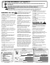
Use only a qualified mechanic for
any adjustments, disassembly or
any kind of repair .
DISCONNECT SPARK PLUG WIRE
BEFORE SERVICING UNIT.
WARNING: TO AVOID PERSONAL INJURY, ALWAYS
TURN MACHINE OFF, MAKE SURE ALL MOVING
PARTS COME TO A COMPLETE STOP.
RECONNECT SPARK PLUG WIRE,
GUARDS, BAG, CAPS AND / OR
HOSE BEFORE STARTING ENGINE.
ENGINE: See engine manufacturer
operator's instructions.
DEBRIS BAG: See page 6.
17.117.1
17.117.1
17.1
1717
1717
17
DANGER
DANGER
KEEP HANDS and FEET AWAY
KEEP HANDS and FEET AWAY