Part No 521302
Form No F101910A
10
HP Owner’s Manual
CUTTING OPERATION
CAUTION: Shut off the blades when crossing gravel drives, walks
or roads and under all conditions where thrown
objects might be a hazard.
CLEARING A CLOGGED CUTTING DECK: Turn engine off and wait for blade to stop completely. Disconnect
spark plug wire and place the unit in gear to prevent the unit from rolling.
Wearing durable gloves, remove clog. Danger, the clog may contain sharp materials. Reconnect spark plug
wire.
CAUTION: Use extreme care when operating the blades. Inspect the work area for foreign objects that could
cause damage to the unit or injure the operator if struck by the blade. Never operate the blades with bystanders in
the work area.
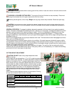
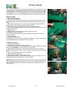
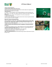
GENERAL OPERATION: To engage the blades, depress the operator’s left hand control lever against operator’s
handle. The blade is disengaged by releasing this lever. (See Fig. 16-5 next page) To engage the wheel drive lift the
operator’s right hand control lever against operator’s handle. The drive is disengaged by releasing this lever.(See
Fig. 16-6 next page) Ground speed can be varied by shifting gears as described on page 11. To begin cutting,
engage the blade lever, allow the blade to spin up to speed, and engage the wheel drive to begin moving forward into
the material to be cut.
NOTE: Do not engage blades during transport between work sites. The blade should remain disengaged at all times
when work is not being performed.
The best performance is achieved when cutting in dry conditions. If the deck becomes choked with grass or debris
during operation, back unit off of debris allowing machine to clear itself and continue cutting, or shut the unit off and
clear the clog by hand (See above). A drop in engine RPM or a noticeable change in engine sound is usually a good
indicator of a clogged discharge or other interference.
Under most conditions cutting should be done in second or third gear. The quality of the cut produced is directly
related to the unit's ground speed during cutting. If the quality of the cut is not satisfactory (i.e. material left standing)
you should shift into a lower gear during cutting.
CUTTING HEIGHT ADJUSTMENT
CAUTION: DO NOT make cutting height adjustment when
engine is running.
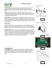
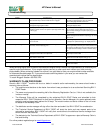
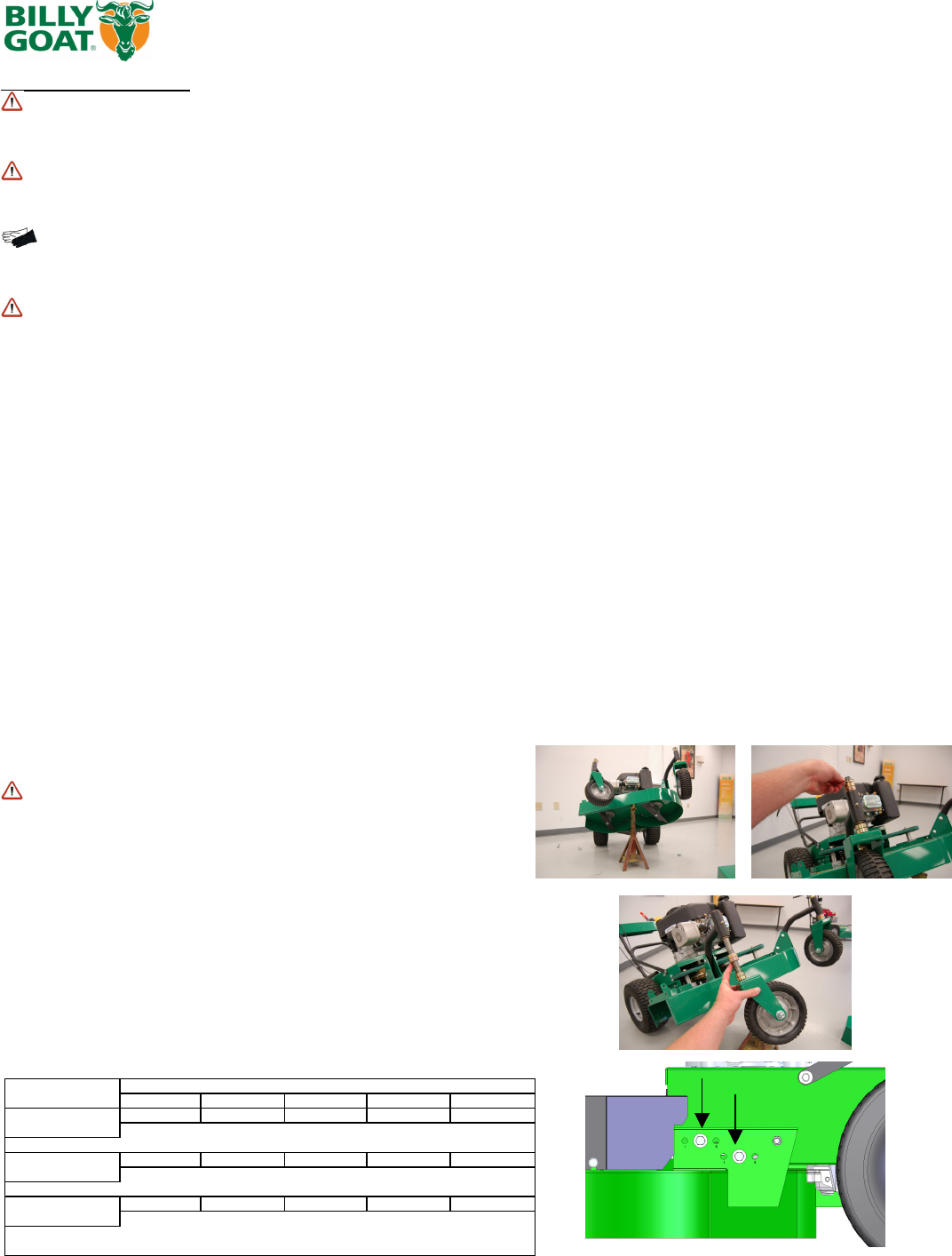
Cutting height can be adjusted from 1.5" to 3.5" by placing spacers
above or below caster spindles. For easiest adjustment change the
height on one side at a time. To change cutting height, tilt the unit
back, remove lynch pin, remove all spacers then set if off to the side,
remove caster rig, add or subtract spacers, reinstall caster rig, place
remainder of spacers if any, then reinsert lynch pin (see figure right).
Repeat this step on other side. For finer adjustment relocate the
bolts located on the deck brackets to change the angle of the deck.
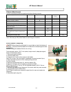
See the chart below for the corresponding positions and cutting
heights
NOTE: Be sure that the spacers are even on both casters. Running
the deck out of level will result in poor cut quality.
Cutting Height Chart Number of spacers below caster arm
0 Spacers 1 Spacer 2 Spacers 3 Spacers 4 Spacers
Bolts in position #1 1.5" 1.88" 2" 2.3" 2.5"
on deck
Bolts in position #2 1.5" 2" 2.4" 2.75" 3"
on deck
Bolts in position #3 1.75" 2" 2.5" 3" 3.5"
on deck
Note
that all cutting heights will be from the lowest cutting edge with standard blades


