


Part No. 360178 Form No. F012302A
Page 3 of 12
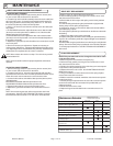
PUT OIL IN ENGINE BEFORE STARTING
Read all safety and operating instructions
before assembling or starting this unit.
Engine
Manual Per
Model
These items should be included in your carton. If any
of these parts are missing, contact your dealer.
ASSEMBLY
PACKING CHECKLIST
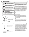
GENERAL SAFETY
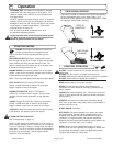
For your safety and the safety of others, these directions should be followed:
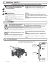
Use of Ear Protection is recommended while
operating this machine.
Use of Eye and Breathing protection is recommended
when using this machine, especially in dry and dusty
conditions.
·DO NOT place hands or feet underneath unit, near debris
outlet or near any moving parts.
·DO NOT start engine without tine height adjust lever in up
position and clutch bail disengaged.
·DO NOT start or operate machine with guards removed.
·DO NOT perform any service on the unit without removing
the spark plug wire.
·DO NOT operate a machine that exhibits excessive vibration.
·DO NOT operate this machine on slopes greater than 19°.
·DO NOT use this unit on any surface other than grass lawns.
·DO NOT allow children to operate this equipment.
-DO read all maintenance and operating instructions before
begining work.
-DO read all engine manufacturers operating and maintenance
instructions.
-DO inspect lawn before begining work. Remove all rocks, wire,
string, or other objects that can present a hazard during work prior to
starting.
-DO identify and mark all fixed objects to be avoided during work,
such as sprinkler heads, water valves, buried cables, or clothes line
anchors, etc.
9
10
11
Do not operate this machine without first reading
owner's manual and engine manufacturer's manual.
Check
Check
Briggs & Stratton
5.5 Intek OHV
Per Model
Honda 5.5 OHV
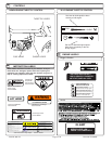
Your Billy Goat EZ-Air aerator is shipped from the factory in one
carton, completely assembled.
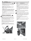
3. SECURE the upper handle by positioning the lowermost mounting hole
over the chosen handle mounting stud and tightening the hand knob on
the handle pivot bolt to secure the handle in position.
4. REPLACE the lock nuts that were removed in step one and fully
tighten them to complete securing the handle in place.
5. ATTACH the lift rods, one on each side of the unit. Remove the hair
pins that are shipped in free end of the rods. Pivot the rods up and along
the side of the unit and slip the free end of the rod into the lift link bars
one on each side of the unit. With the rods in position, replace the hair
pins in the holes that they were removed from to lock the lift rods in
place.
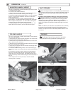
5. CHECK engine oil level and fill to proper level. See engine owners
manual for type and amount of oil to use. Move the tine height adjust
lever to the down position, to level engine during checking.
6. CONNECT spark plug wire. HONDA ONLY: Set the engine stop switch
to the on position. You will use the stop switch on the handle during
operation.
Literature
Assembly
360177
Wearing gloves is recommended while
operating this machine.
Check
Owner's
Manual
360178
Check
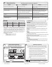
EU Declaration
of Conformity &
EU Distributor
List 360194
Check
Warranty
Card 400972
1. REMOVE lock nuts from the upper handle mounting stud. These
will be reused.
2. UNFOLD the upper handle and pivot it back into the operating
position. NOTE: There are two height positions that the handle can
be set in. The lower stud places the handle in the highest position
the upper stud places the handle in the lowest operating position.