


Part No. 360251 Form No. F031005B
Page 7 of 12
Never store engine indoors or in enclosed poorly ventilated areas
with fuel in tank, where fuel fumes may reach an open flame, spark or
pilot light, as on a furnace, water heater, clothes dryer or other gas
appliance.
If engine is to be unused for 30 days or more, prepare as follows:
Remove all gasoline from carburetor and fuel tank to prevent
gum deposits from forming on these parts and causing possible
malfunction of engine. Drain fuel outdoors, into an approved
container, away from open flame. Be sure engine is cool. Do not
smoke. Run engine until fuel tank is empty and engine runs out of
gasoline.
NOTE: Fuel stabilizer (such as Sta-Bil) is an acceptable alternative in minimizing
the formation of fuel gum deposits during storage. Add stabilizer to gasoline in
fuel tank or storage container. Always follow mix ratio found on stabilizer
container. Run engine at least 10 min. after adding stabilizer to allow it to reach
the carburetor.
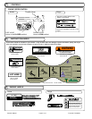
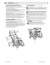
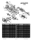
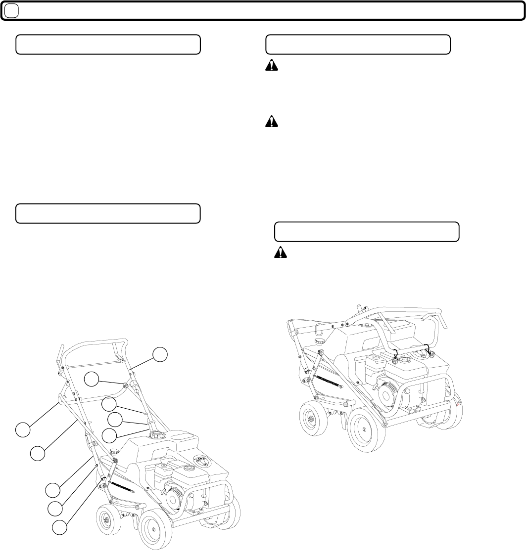
This unit is equipped with a folding upper handle for easier storage.
TO FOLD THE HANDLE (See Fig. 4) :
1. Remove the latch pin (item 47) from the lift rod (item (46).
2. Remove the lift rod from the lift handle (item 52) then pivot the lift
rod toward the front of the unit. Repeat same steps on other side.
3. Slide handle lock loops (item 118) and secure on the loop pin
(item 53). Repeat same steps on other side.
4. Fold the upper handle (item 48).
FOLDING HANDLE
OPERATION continued
16
UNIT STORAGE
NEVER PARK THIS UNIT ON A SLOPE OF ANY KIND.
Always keep tines in the up position when parking the unit.
PARKING
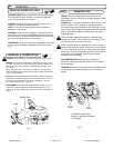
This unit is equipped with a height adjustable upper handle to allow
for multiple operator heights.
TO ADJUST THE HANDLE HEIGHT:
1. Remove the lock nuts (item 50) that secure the handle, one on
each side, to the lower handle mounting studs.
2. Loosen the handle mounting bolts (item 51), one on each side,
(See Fig. 3) and push the handle out and away from the lower
handle mounting studs.
3. The handle is now free to rotate. Adjust the handle to the
desired height. The BOTTOM handle mounting stud coresponds
with the highest handle position. The TOP handle mounting stud
coresponds with the lowest handle mounting position.
4. Completely tighten the handle mounting bolts (item 51), and
replace the lock nuts (item 50) to secure the handle in place.
ADJUSTING HANDLE HEIGHT
46
52
48
47
118
82
83
53
Fig. 3
Fig. 4
50
51