


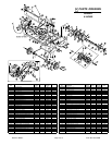
Part No. 360251 Form No. F031005B
Page 11 of 12
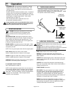
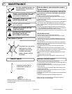
MAINTENANCE
17
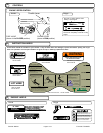
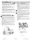
BELT AND CHAIN TENSION ADJUSTMENT
1. Wait for engine to cool and disconnect spark plug.
2. Remove the top guard by removing the four nuts, two on each side,
that secure it to the frame.
3. Slide the belt off of the engine drive pulley, and off of the jackshaft
drive pulley.
4. Continue sliding the belt along the jackshaft to the right jackshaft
bearing away from the pulley and sprockets.
5. Using a 9/16" wrench, remove the two bolts and nuts that hold the
jackshaft bearing in place.
6. Carefully lift the jackshaft up until the belt can be slid out underneath
the bearing.
7. Slide the new belt in place over the jackshaft.
8. Replace and tighten the bolts and nuts holding the jackshaft bearing
in place. Be sure that the jackshaft is aligned straight across between
both bearings.
9. Slide the belt along the jackshaft and over both engine and jackshaft
pulleys. Be sure the idler pulley is positioned on the flat side of the belt.
10. Check proper belt tension. See BELT TENSION ADJUSTMENT in
this manual.
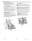
DRIVE BELT REPLACEMENT
ADJUSTING BELT TENSION-
1. Remove the top guard (item 3) by removing the four nuts(item 87),
two on each side, that secure it to the frame.
2. Locate the top of the belt idler assembly where the clutch cable (item
55) is secured in place. A properly tensioned belt should stretch the
idler spring (loacted next to the idler pulley) between 1/4" - 3/8" when
the clutch bail (item 54) is held in the drive position.
3. Using a 1/2" wrench loosen the two nuts that secure the cable (item
55) in place.
4. TO INCREASE belt tension adjust these two nuts so that the cable
(item 55) is secured in place with an additional 1/4" of the threaded
adjuster at the top of the assembly.
TO DECREASE belt tension adjust these two nuts so that the cable
(item 55) is secured in place with 1/4" less of the threaded adjuster at
the top of the assembly.
5. Replace the guard (item 3) and reinstall the four nuts (item 87) that
secure it in place.
6. Run the unit to test your adjustment. Repeat as necessary to
achieve proper adjustment. A properly adjusted belt will pull the unit up
a 15 degree slope when clutched without any belt slip, and will declutch
and stop the unit completely when the clutch is released.
NOTE: Never release the clutch on a slope. The unit is heavy and will
free wheel down hill.
NOTE: A worn belt will not allow for proper adjustment and must be
replaced.
ADJUSTING CHAIN TENSION-
1. Remove the top guard (item 3) by removing the four nuts(item 87),
two on each side, that secure it to the frame.
2. Locate the bolt (item 31, 33) and nut (item 80) that hold each idler
sprocket to the frame of the unit. One idler sprocket sets tension on the
wheel drive chain and one sets tension on the tine drive chain.
3. Loosen the bolt and nut and slide the idler sprocket (item 29) in the
desired direction.
INCREASED TENSION: Slide the sprocket to the rear.
DECREASED TENSION: Slide the idler sprocket to the front.
4. Tighten the bolt and nut to secure the sprocket in place.
5. Replace the guard and reinstall the four nuts that secure it in place.
NOTE: Over tensioning the chain will cause premature chain and
sprocket wear. DO NOT OVER TENSION THE CHAIN. A properly
tensioned chain will have slack of 1/4"-3/8" when moved by hand.
NOTE: This procedure will work to change the wheel drive chain
or the tine drive chain.
1. Wait for engine to cool and disconnect spark plug.
2. Remove the top guard by removing the four nuts, two on each side,
that secure it to the frame.
3. Roll the unit until the master link of the chain that you want to replace
is exposed near the jackshaft sprocket.
4. Release the tension on the chain. See CHAIN TENSION ADJUST-
MENT in this manual.
5. Using a screwdriver or similar device remove the spring clip that
secures the master link in the chain.
6. With the master link removed unwind the chain from the two sprock-
ets that it connects.
7. Carefully string the replacement chain around the same two sprock-
ets and reconnect it with the new master link provided with your
replacement chain.
8. Re set the tension on the chain.
9. Replace the guard and reinstall the four nuts that secure it in place.
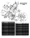
CHAIN REPLACEMENT
Engine (See Engine Manual)
Check engine oil
Check gear reduction oil level
Grease bearings (See Lubrication)
Inspect belt
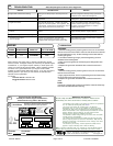
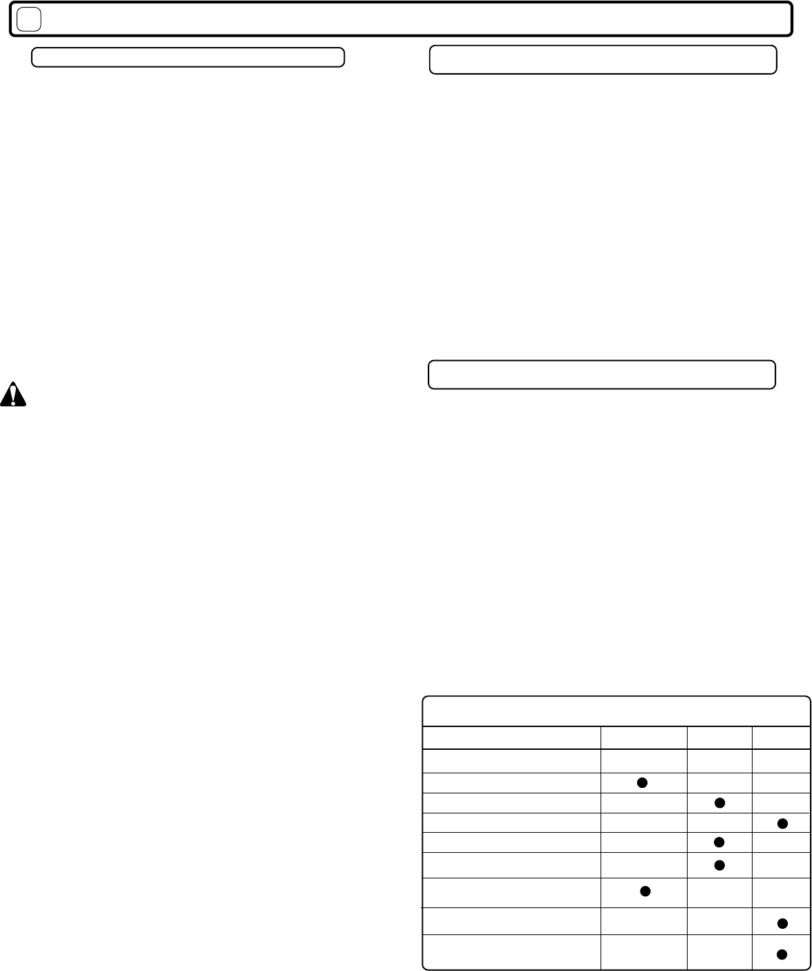
Maintenance Operation
Follow these hourly
maintenance intervals.
Maintenance Schedule
Every
25 hrs
Every Use
(Daily)
Inspect for loose, worn,
or damaged parts
Throughly clean all debris from unit
and tine reel.
Oil chains (See Lubrication)
ENGINE MUST BE LEVEL WHEN CHECKING OR FILLING OIL
Every
50 hrs
Check tine reel nut torque. Torque to
minimum 100 ft.lbs