2. Replacement of the cooling liquid
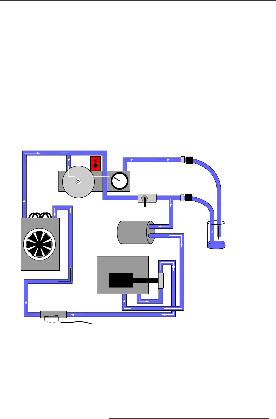
2. Push the valved fitting of the filled tube into the Inlet ’IN’ ofthe coolingcircuit. Ensure theloose endof the tuberemains immersed
in the liquid.
3. First, immerse the loose end of the other tube into the a bottle filled with a little liquid, to prevent the inlet tube from draining, and
next push the valved fitting into the Outlet ’OUT’ of the cooling circuit.
4. Switch on the projector. After projector boot-up procedure, the internal pump will automatically start sucking-up the fresh liquid
supply and expelling aged liquid into the empty bottle.
5. Timely switch Off the projector to prevent the fresh liquid level dropping below the free tube inlet. This again to avoid unwanted
air being sucked into the cooling loop.
6. Continue with the procedure for expelling unwanted air.
2.3 Expelling of any unwanted air
Expelling of any unwanted air
1. Close the vane, if not yet closed.
2. Put the free tube inlet of the tube connected to the ’OUT’ outlet into the remaining fresh liquid.
The liquid cooling loop - Expelling air bubbles
Engine
Pump
Vane
Outlet
Inlet
Expansion Vat
Manometer
Waterflow Sensor
Heat
Exchanger
to SMPS Control
Light Pipe
entry
Pressure relief
valve (3 Bar)
Image 2-4
Unwanted bubbles expelling (principle)
R59770032 COOLING LIQUID REFILL 24/08/2006 7


