


Section 4
Operation
Operation 4-1MN2403
Operator Control Panel
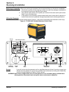
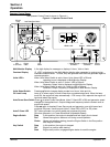
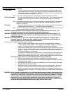
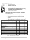
The Operator Control Panel is shown in Figure 4-1.
Figure 4-1 Operator Control Panel
STOP
ON
CHOKE
+
−
−
+
Engine
Switch
Auto
P−Save LED
Multi Monitor Display
Oil Level
Lamp
Units LED’s
Key
Switch
Units
Select
Switch
Auto Power Save Switch
NEMA 5−20R NEMA L530R
Ground
Terminal
(−) Battery Charger
Connection
DC
Breaker
STOP
ON
START
BATTERY CHARGE ONLY
DC 12V − 8.3A
~ AC OUTPUT
(+) Battery Charger
Connection
Multi Monitor Display A five digit display for messages or display of Hours, Volts or Hertz.
Overload Display “O_LOD” is displayed on the Multi Monitor display when generator is running and an
overload condition exists. To reset, Stop the generator and Start the generator again to
resume operation.
Units LED’s When Units Select Switch is set to Hours, Units Hours LED is ON and
operating hours is displayed on Multi Monitor Display.
When Units Select Switch is set to V, Units V LED is ON and
Generator Output Volts is displayed on Multi Monitor Display.
When Units Select Switch is set to Hz, Units Hz LED is ON and
Generator Output Frequency is displayed on Multi Monitor Display.
Units Select Switch Pressing
Switch changes display modes from Hours, Volts and Hz.
Oil Level Lamp Lamp is on when engine oil level is less than a predetermined level. When the lamp
turns ON, the engine will stop automatically. If Oil Lamp is ON, replenish the engine oil
level and restart the engine.
Auto Power Save Switch Press
to select Power Save Mode, (Auto P−Save LED is ON) and generator speed
changes for the applied load. Output voltage and frequency remain constant even at
engine idle speed.
Press
again to deselect Power Save mode and generator runs at full speed and
produces full power. Use this mode (Auto P−Save LED is OFF) for DC power.
Auto P−Save LED OFF when generator runs at full speed and produces full power.
ON when generator is in Power Save Mode (Adjustable Speed).
Engine Switch Stop In this position, the engine is stopped and fuel supply line is closed.
Run Allows the engine to start and run during normal operation.
Choke Allows cold weather starting, place the Engine Switch in the Run position
after engine is started.
Key Switch Stop In this position, the engine is stopped.
ON Engine run position after starting.
Start Engine start position, engages engine starter to crank the engine.