


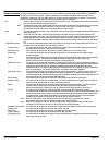

4‐16 Operation MN2408
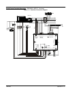
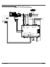
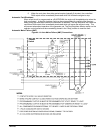
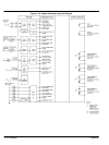
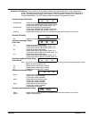
When the controller is applied in an Auto Mains Failure (AMF) application with a transfer switch,
it must be wired as shown in Figure 4‐14. Programmable output #3 must be selected for Utility
Ready To Load and programmable output #4 must be selected for Gen Ready To Load. After the
controller is programmed, the AMF sequence of operation will be as follows:
Utility Normal Condition:
1. Remote Start input signal (terminals 16 & 17) is not activated (i.e. normal).
2. Utility Ready To Load output is energized (i.e. signal to transfer switch to transfer to
utility power).
3. Generator Ready To Load output is de-energized.
Utility Power Failure Conditions:
1. Remote Start input signal is activated (i.e. remote start contact closes when utility
power fails, as sensed by utility voltage sensor).
2. Engine starts after the Engine Start Delay timer (Utility Ready To Load output stays
energized).
3. After the engine has started and the generator output rises above the programmed
voltage and frequency limits, a Warm-Up timer is initiated.
4. After the Warm-Up timer expires the Utility Ready to Load output de-energizes and the
NEUTRAL Delay timer is initiated.
5. After the NEUTRAL DELAY timer expires the Gen Ready to Load output energizes to
signal the transfer switch to transfer to the generator supply. Note: The neutral delay
function is only operative with an electrically-held type transfer switch mechanism
(ie. electrical contactor type).
Utility Power Restored:
1. Remote Start input signal is removed and the Return Delay timer is initiated (i.e. Utility
Voltage returns to normal and the Utility voltage sensor contact opens).
2. After the Return Delay timer expires, the Generator Ready to Load output
de-energizes and the Neutral Delay timer is initiated.
3. After the Neutral Delay timer expires the Utility Ready to Load output energizes to
signal the transfer switch to transfer to the utility supply. Note: If the generator has a
shutdown during the Return or Neutral Delay periods, the timers are bypassed, and the
Utility Ready to Load output immediately energizes.
4. The generator Cool down Timer starts after the Return Delay timer.
5. The generator stops after the Cool down Timer.
Load Test Push-button Operation
1. When the Load Test pushbutton is pressed, the logic will internally simulate receiving a
remote start input.
2. Engine starts after the Engine Start delay timer.
3. After the engine has started and the generator output rises above the programmed
voltage and frequency limits, a Warm-Up timer is initiated.
4. After the Warm-Up timer expires the Utility Ready to Load output de-energizes and the
Neutral Delay timer is initiated.
5. After the Neutral Timer expires the Gen Ready To Load output energizes to signal the
transfer switch to transfer to the generator supply.
Note: If a generator shutdown occurs during a Load Test Operation, the Load Test mode will be
de-activated.
When Auto Mode is restored (after Load Test Operation) the following occurs:
1. Simulated Remote Start input signal is removed.
2. Gen Ready To Load output de-energizes, and Neutral Delay timer is initiated.
3. After the Neutral Delay timer expires The Utility Ready To Load output energizes to
signal the transfer switch to transfer to the utility supply.
4. The generator Cool down timer starts timing following the transfer to the utility supply.
5. The generator stops after the Cool down timer.