


Receiving & Installation 3‐7MN2408
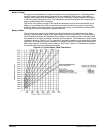
Example: Determining Pipe Size for Natural Gas
A generator has a 16Hp engine 60 feet from the supply.
Determine the supply pipe size for Natural Gas fuel.
16 x 10,000 = 160,000 BTU's / per hour for proper operation.
160, 000
1, 096
Ă +Ă 146ĂcubicĂfeetĂperĂhour.
From Table 3‐6, a 60 foot run requires a minimum 1” pipe at full engine load.
Natural Gas Connections
The incoming pressure must be 11 inches water column (6 oz. pressure).
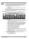
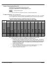
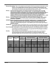
Table 3‐5 Natural Gas Flow Rate (Cubic Feet per Hour) per Pipe Length
Pipe
Length
(Feet)
Iron Pipe Size
1
/
2
3
/
4
1 1-
1
/
4
1-
1
/
2
2 2-
1
/
2
3 4 6 8
15 73 165 332 722 1174 2386 3704 6253 13352 37229
30 50 115 232 515 818 1712 2646 4521 9331 26330 53728
45 41 95 191 418 673 1419 2213 3752 7600 22462 43867
60 37 83 166 366 587 1241 1924 3319 6542 18595 37999
75 74 149 332 524 1077 1684 2886 5772 16652 33959
90 67 137 298 433 962 1501 2597 5291 15200 31025
105 63 126 274 885 1376 2357 4906 14064 28715
120 115 260 404 827 1289 2213 4618 13160 26859
150 105 233 366 750 1174 2011 4185 11775 24050
180 96 216 337 693 1077 1876 3848 10736 21934
210 89 197 308 635 991 1712 3559 9937 20298
240 183 289 596 933 1616 3357 9235 18990
270 171 274 558 875 1520 3127 8658 17903
300 164 260 524 827 1433 2886 8177 16998
Note: Almost all operation problems are related to the installation techniques used. Do Not
guess, be sure pipe size is adequate for required flow rate.
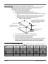
1. Connect the proper size gas pipe at the Inlet Connection to the Fuel Lock Solenoid.
Connect the Natural Gas pipe line shown in Figure 3‐3 using the correct size pipe for
the required flow rate and length of pipe. Refer to Table 3‐5 for pipe size. Be certain
that all connections are sealed and no leaks are present. The installer must ensure
that all gas connections comply with all building codes.
2. Verify Fuel Supply Pressure
Prior to initial operation of generator, verify that fuel system pressure is 11 Water
Column (6 oz. pressure) and fuel pipe sizes comply with Table 3‐5.
3. Proceed to Electrical Connections.
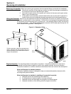
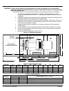
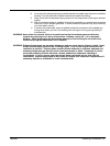
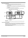
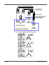
Figure 3‐3 Gas Line Connections
Solenoid, Fuel Lock
Inlet Connection
Air Cleaner
Carburetor
Mounting Bracket
Additional Valve
(Safety Shutoff Valve)
Supply Piping
U.L. requires a second shutoff valve and regulator to be installed in the supply piping to
control the gas supply to the generator.
Additional Regulator
(11 - 14” water column pressure)
External Supply Piping (by installer)
To Inlet
Connection