


INTERNAL SWITCHES
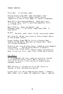
Damping
Control -To allow the controller to provide automatic
tuning for processes with varying heating characteristics and
with varying heating capabilities, the 6050 offers three
damping choices:
High damping: for over-powered heating systems,
systems with multiple heat lags, and/or poor
coupling between the heater and the temperature
sensor.
Normal: for most standard processes where the
heater is properly sized for the system and
there is good coupling between the heater and
the temperature sensor.
Low damping: for adequately powered systems
with excellent coupling between the heater and
the temperature sensor where quick response and
the tightest possible temperature control are
desired.
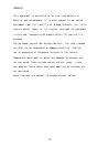
Keypad Security -Switch 2 in the open position locks the
operator out of access to all parameters except set point.
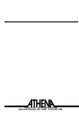
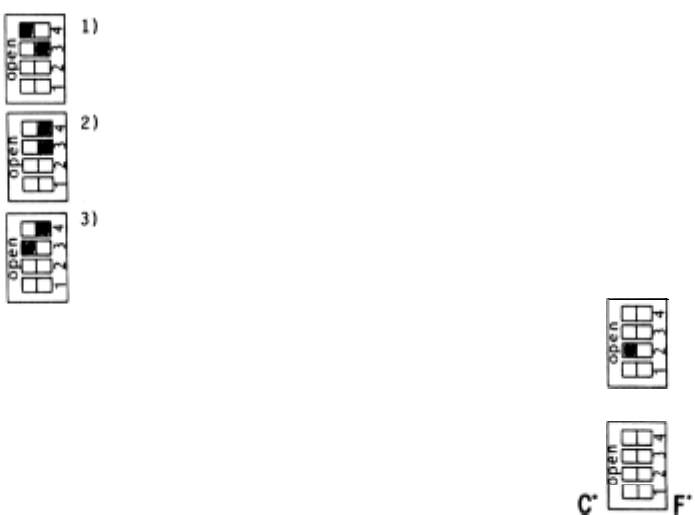
CELSIUS/FAHRENHEIT DISPLAY SECTION
Switch 1 allows both displays to read in degrees Celsius or
Fahrenheit, and is indicated on front panel
LED's.
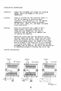
WIRING THERMOCOUPLE CIRCUITS
Before wiring, check thermocouple and extension wire to make
sure that they conform to the appropriate thermocouple type
specified on the serial number tag. In thermocouple
circuits, the negative lead is colored red. Extension wires
must
be the same alloy and polarity as the couple. The
thermocouple circuit resistance should not exceed 100 OHMS.
Do not run thermocouple leads in the same conduit as the
power lines. If shielded thermocouple is used, terminate the
shield only at the controller end using the corner screw
provided for that purpose.
STANDARD THERMOCOUPLES
I.S.A.
TYPE
MATERIALS
COLOR CODE
J
Iron Constantan
(I/C)
White(+)
Red(-)
K
Chrome1 Alumel
(C/A)
Yellow(+)
Red(-)
8