


THERMOCOUPLE PLACEMENT
Proper thermocouple placement can eliminate many problems in
the system. The probe should be placed so that it can detect
any temperature change with minimal thermal lag. In a process
that requires fairly constant heat output, the probe should
be placed close to the heater. In processes where the heat
demand is variable, the probe should be close to the work
area. Some experimenting with probe location is often needed
to find its optimum position.
In
a bath process, addition of a stirrer will help to
eliminate thermal
lags.
Since the thermocouple is basically
a point measuring device, putting more than one
in parallel will provide an average temperature
produce better results in air heated processes.
thermocouple
reading and
NOTE: If controls with
"F"
or
"S"
outputs drive
grounded or hot input terminals
(not
floating),
thermocouple must be used. Otherwise, when both
loads with
an isolated
input and
output are grounded, ground loop currents
will
result,
causing errors and controller damage.
Standard thermocouple limits of error are 4°F or 0.75% of
sensed temperature (half that for special) plus drift caused
by improper protection or overtemperature. This is far
greater than controller error, and can not be corrected at
the sensor except by selection and replacement.
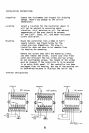
Start-Up
Before line voltage is applied, double-check the following:
Make sure the thermocouple type is correct, and
properly connected (see section on thermocouples)
to terminals 1 and 2 (red on
2).
Make sure there is no AC or DC voltage leading or
arcing to T/C.
Make sure the proper terminals are selected for
line voltage.
(8
&
9 for
12OV,
8
&
10 for
24OV)
Check to assure there are no heater shorts, or
shorts to ground, and no bare wires or frayed insulation.
Make sure correct plug-in module is used.
9