


GB - 20
ATTACHMENT DRIVE BELT
REPLACEMENT
Remove Attachment Drive Belt
(Figures 20 and 21)
1. Shut off engine, remove key, disconnect spark
plug wire and allow unit to cool completely.
2. Remove two screws securing belt cover to unit
and remove belt cover.
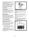
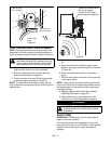
3. Remove spring pin from chute crank and
seperate (Figure 20).
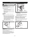
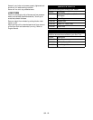
4. Remove belt fingers by removing cap screws
mounting belt fingers to engine (Figure 21)
IMPORTANT: To avoid bending bottom cover, remove
the cover before separating the blower housing from
the unit.
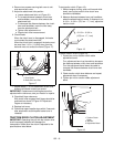
5. Support Sno-Thro frame and housing.
6. Remove top two cap screws and loosen lower
cap screw holding blower housing to frame on
each side.
7. Remove attachment drive belt from engine
sheave (it may be necessary to turn engine
sheave using recoil starter handle).
8. Separate housing from unit. Lower handlebar on
floor.
9. Remove attachment drive belt from lower pulley.
Replace Attachment Drive Belt
1. Place new belt onto lower pulley and while
holding brake out of way, tip unit together.
NOTE: Engage attachment clutch lever while
connecting housing to frame to hold brake out of the
way.
2. Secure blower housing to frame with cap screws
removed in step 6 of Remove Attachment Drive
Belt on page 20.
3. Place belt onto engine sheave.
4. Replace belt fingers.
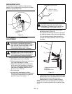
IMPORTANT: BELT FINGERS MUST BE SET as
shown in Figure 22. Improper adjustment may cause
impeller to rotate while attachment clutch is
disengaged.
5. Adjust clutch per Attachment Clutch/Brake
Adjustment on page 18.
6. Replace belt cover and secure with cap screws.
7. Run-in the drive belt according to instructions in
Run-in Attachment Belt on page 10 and then
check attachment drive clutch adjustment. See
Attachment Clutch/Brake Adjustment on page 18.
CAUTION: Always support Sno-Thro frame
and housing when loosening the cap screws
holding them together. Never loosen cap
screws while unit is in service position.
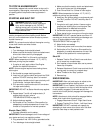
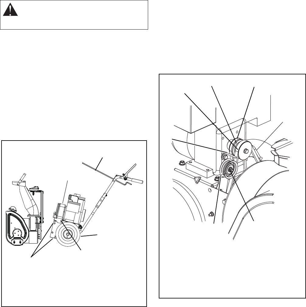
Figure 20
1.Chute Crank
2.Belt Cover
3.Bottom Cover
4.Belt Cover Screw
5. Housing Bolt Holes
OS7240
1
3
4
5
2
Figure 21
1.Attachment Drive Belt
2.Engine Sheave
3.Traction Drive Belt
4.Attachment Idler Nut
5.Attachment Belt Idler
6.Belt Finger
1
2
3
4
5
6
6