


GB - 19
4. Remove two screws securing belt cover to unit
and remove belt cover.
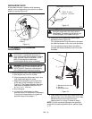
5. Adjust the attachment idler position.
a. Loosen attachment idler nut (Figure 21).
b. To increase distance between clutch lever
and handlebar, move the idler towards the
attachment belt.
c. To decrease the distance between the clutch
lever and handlebar, move the idler away
from the attachment belt.
d. Tighten idler adjustment nut.
e. Check clutch lever measurement.
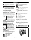
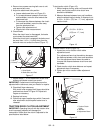
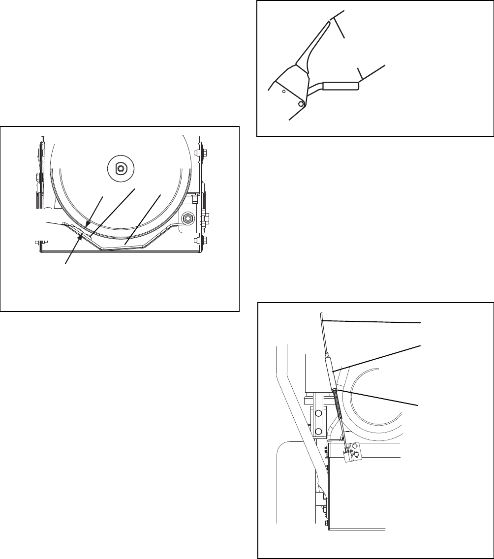
6. Check Brake
When the clutch lever is disengaged, the brake
must contact the attachment belt.
When the clutch lever is engaged, the brake must
be more than 1/16 in. (1.6 mm) away from the
belt and must not contact the frame (Figure 17).
7. Repeat steps 5 – 6 until attachment clutch lever
distance and brake contact are correct.
IMPORTANT: If attachment clutch/brake cannot be
adjusted within tolerances, see your Dealer for repairs.
8. Check belt finger clearance.
With clutch lever engaged, belt fingers should be
positioned as shown in Figure 22. Adjust belt
fingers as necessary.
9. Replace belt cover.
10. Check that auger/impeller stops within 5 seconds
after attachment clutch/impeller brake lever is
released.
TRACTION DRIVE CLUTCH ADJUSTMENT
IMPORTANT: Operating the unit with the traction drive
clutch improperly adjusted will damage the
transmission. Make sure the clutch is adjusted to the
specifications listed below.
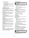
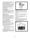
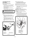
To test traction clutch (Figure 18):
1. Without engine running, push unit forward while
slowly moving the traction drive clutch lever
toward the handlebar.
2. Measure distance between lever and handlebar
when the wheels begin to brake. If distance is not
6-1/8 in. - 6-3/4 in. (15,5 cm - 17,1 cm), adjust the
traction clutch.
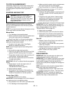
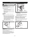
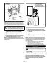
To adjust traction clutch (Figure 18):
1. Loosen jam nut on traction clutch cable
adjustment barrel.
Turn adjustment barrel up the cable to decrease
the distance between clutch lever and handlebar.
Turn the adjustment barrel down the cable to
increase the distance between clutch lever and
handlebar.
2. Check traction clutch lever distance and repeat
adjustment steps if necessary.
3. Tighten jam nut on traction cable adjustment
barrel.
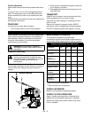
Figure 17
1.Drive Brake
2.Brake Shoe and Pad
1
2
1/16 in.
(1.6 mm)
Traction Clutch Lever
OS2490
Figure 18
6-1/8 in. - 6-3/4 in.
(15,5 cm - 17,1 cm)
Figure 19
1.Traction Clutch
Cable
2.Jam Nut
3.Adjustment Barrel
1
3
2