


GB - 13
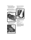
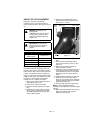
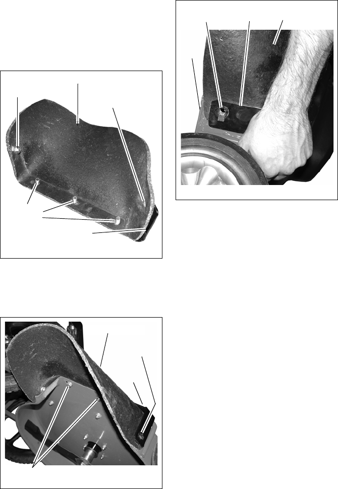
Discharge Chute Installation
1. Place mower in the Service Position.
See SERVICE POSITION on page 20.
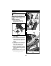
2. Remove flanged lock nut and round
head square neck bolt from front of
discharge chute. See Figure 12.
NOTE: DO NOT remove flanged lock nut and
round head square neck bolt securing
together rear of discharge chute and support
plate.
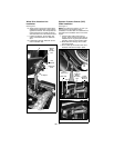
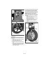
3. Remove three flanged nyloc nuts from
round head square neck bolts at center
of discharge chute.
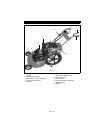
4. Position chute and support plate over
discharge opening in mower deck. See
Figure 13.
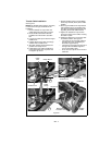
5. Install three flanged lock nuts on round
head square neck bolts at center of
discharge chute. Do not tighten.
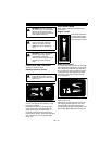
6. Align front of chute and support plate
with hole in deck and install round head
square neck bolt and flanged lock nut.
See Figure 14.
7. Tighten chute mounting hardware
installed in steps 5 and 6.
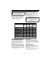
Wheel Drive Adjustment
1. Adjust fine adjustment knobs (Figure 26)
as necessary to achieve 1/8" – 1/4"
(3mm – 6mm) drive roller gap at wheels.
See Figure 27.
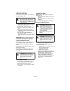
Engine Preparation
1. Check engine oil level and add if
necessary. See engine manual.
2. Fill fuel tank.
3. Connect spark plug wire.
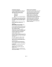
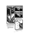
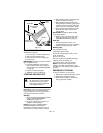
4. Check the Operator Presence Control
(OPC) feature. Try starting the engine
without the OPC lever (Figure 15, Item
1) held against the handlebar. Engine
must not start. If engine starts, stop
engine and bring the unit to your dealer
for adjustment or repair.
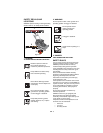
Figure 12
Discharge Chute
Hardware
Removed
Support Plate
Mounting
Bolts
DO NOT
Remove
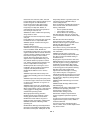
Figure 13
Discharge Chute
Support
Plate
Flanged
Locknuts
See
Figure 14
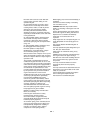
Figure 14
Support
Plate
Discharge
Chute
Mower
Deck
Install bolt
here.