


8 - 37
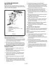
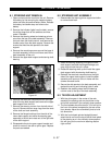
8.1 STEERING UNIT REMOVAL
1. Open and remove the hood from the unit. Remove
the battery by first removing the negative battery
cable and then the positive battery cable. Release
the battery hold down strap and remove the
battery.
2. Remove the indicator lights from the dash, remove
the wiring plugs from all the switches and hour
meter if installed.
3. Remove the steering wheel and steering column
cone from the top of the dash assembly. Remove
the knob from the throttle control, and remove the
throttle control from the dash support. Remove the
screws that hold the side panels to the dash
support.
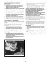
4. Remove the remaining screws around the base of
the dash assembly from the unit frame and lift the
dash assembly off the unit.
5. Remove the upper dash support and steering shaft
bearing.
6. Remove the electrical components from the right
side of the top dash support and remove the upper
dash support from the unit.
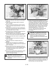
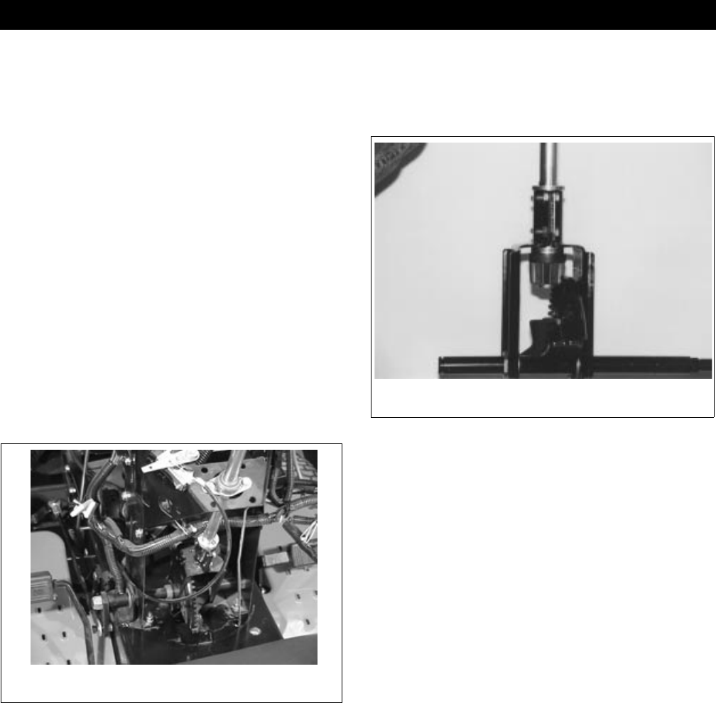
7. Remove the steering rod arm from the left side of
the unit. Remove the two snap rings from the ends
of the shaft and rack assembly.
8. Remove the flange bushings from the side of the
lower dash support and move the steering gear
assembly to the left and rotate out of the right side
of the dash support.
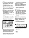
9. Disassemble the pinion gear support bracket and
check for wear on the rack or pinion gear. Replace
the parts as needed.
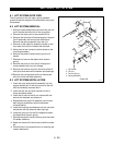
8.2 STEERING UNIT ASSEMBLY
1. Reassemble the steering pinion support and shim
for correct back lash.
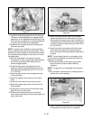
2. Insert the steering assembly through the lower
dash support and add the flange bushings and
snap rings to hold the unit in place.
3. Rotate the steering shaft up and install the upper
dash support with the steering shaft bearing.
4. Reinstall the electrical components on the right
side of the upper dash support. Install the dash
assembly and secure to the unit frame with the
screws removed earlier.
5. Secure the side panels to the dash assembly and
reattach the wiring and indicating lights if used.
6. Reattach the steering wheel and the steering
column cone to the top of the dash assembly.
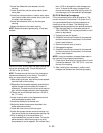
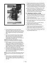
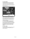
8.3 TIE ROD ADJUSTMENT
1. With the pinion gear in the center of the rack
assembly the steering rod arm should be on the
end of the rack shaft in the vertically down position.
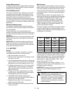
2. The front wheels should be toed in 1/8 of an inch in
the front of the wheel compared to the rear of the
front wheels. Adjust tie rod and ball joints to hold
this dimension.
3. With the front wheels pointed straight forward
attach the tie rod from the top of the left front wheel
to the steering arm in the vertically down position.
this will give you the maximum steering rotation
right and left.
SECTION 8 - STEERING
Figure 44
936-20
Figure 45