7 - 35
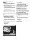
7.2 GEAR TRANSAXLE REMOVAL
(PEERLESS)
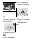
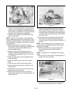
1. Place the unit on a flat surface and remove the
negative lead from the battery and remove the
spark plug lead from the spark plug.
2. Raise and support the rear of the unit. Remove the
rear wheel with associate hardware.
3. Remove the rear tailboard from the unit. Engage
the parking brake and remove the main drive belt
from the input sheave on top of the transaxle.
4. Release the parking brake and remove the brake
rod from the transaxle brake arm.
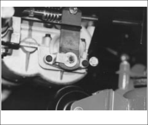
5. Remove the shift link ball joint from the shift arm.
6. Support the transaxle and remove the mounting
hardware and lower the transaxle out of the frame.
7.3 TRANSAXLE TEARDOWN
This unit contains an aluminum tag showing the model
number.
The following steps will need to be taken prior to
disassembly.
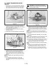
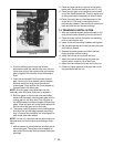
1. Clean the outside surface of the transaxle.
2. Position the shift lever in the neutral position.
3. Remove the set screw, spring and index ball.
4. Remove the neutral start switch.
5. Remove the hex head screws that hold the cover
to the case.
6. Push the shift lever rod while pulling cover off of
the case. The shifting lever may temporarily remain
in the case. Lift off cover.
7. Remove the two brake bracket screws and remove
the brake assembly.
8. Remove the oil from the unit prior to removing the
gear shaft assemblies.
9. Remove the top bearing block on the bull gear of
the differential. Remove the bull gear, bevel pinion
gears with center shaft and the axles.
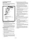
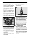
There are 3 shaft assemblies in this transaxle: the
output shaft, the countershaft, and the shifter/brake
shaft assembly. Remove these assemblies as
complete as possible from the case.
As these assemblies are taken apart, lay the parts out
in a systematic order. This will help to make
reassembly easier and inspection of all parts possible.
Clean each part as the parts are laid out.
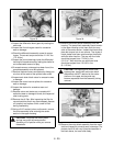
The input shaft can also be removed and inspected or
serviced. Remove the snap ring on the bevel gear and
pull the shaft through the case. The square cut "O" ring
must be replaced if the shaft is removed.
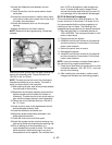
Tecumseh tool part No. 670251, is used for removal
and installation of needle bearings for the input shaft.
The needle bearing on the inboard side is installed
.135-.150" below flush.
Reassembly
1. Apply grease between the bearings in the cover
and install the input shaft, bevel gear and snap
ring.
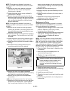
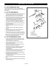
2. Oil both keyways and slide keys and collar on the
shifter/brake shaft.
NOTE:
Assemble the countershaft and the shifter/
brake shaft. Match them together and place into the
housing as a single unit.
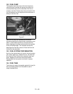
Figure 42


