


GB - 15
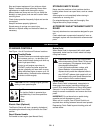
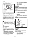
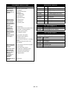
MOWER BLADE
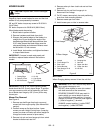
See figure 8.
Regularly check mower blades for wear and that lock
washer is fully compressed by hardware.
28" and 32" decks: torque cap screw to 25-30 lbf-ft
(34-47 N•m).
30" decks: torque nut to 50-60 lbf-ft (68-81 N•m).
When blade needs sharpening:
1. Block blade to prevent rotation.
2. Remove hardware and blade from shaft.
3. Sharpen the beveled edges of the blades in a
straight line. Do not change the angle of the
beveled edge.When blade becomes less than
2.00" wide, discard the blade. Make sure the
sharpened blades are balanced. Balance must
be held within 1.3 inch ounces.
4. Install blade, lock washer, and tighten hardware
to torque listed above.
IMPORTANT: If mower is used under sandy soil
conditions, replace blades when air lifts become
eroded.
IMPORTANT: On 28" & 32", when replacing blade,
blade should be 3/8" (9 mm) above flange. To position,
turn cap screws on each end of blade tray until both
tips of blade clear flange by 3/8" (9 mm) all the way
around pan.
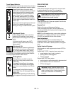
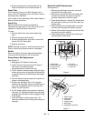
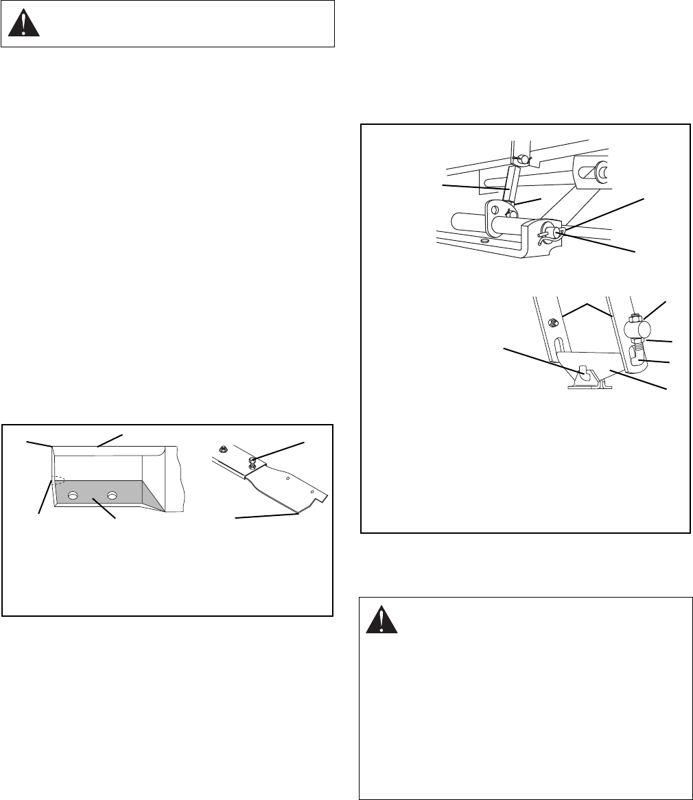
Mower Pan Removal
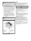
See Figure 9.
1. Remove rear belt finger from back cover and
mower belt from engine pulley (See Mower Belt
section).
2. Position mower on flat level surface. Lower
mower pan with Height Control lever. (Lowering
mower pan down on blocks will relieve weight on
linkage and make removal of pins easier).
3. Remove hair pin and rear hanger pin from swivel
bracket to disconnect rear link.
4. Remove cotter pin from clutch rod and rod from
clutch link.
5. Remove hair pin and front hanger pin to
disconnect front linkage.
6. On 32" mower, remove hair pins and positioning
arms from front mounting bracket.
7. Remove mower pan from rider.
8. Install mower pan on rider in reverse order.
BATTERY
When Charging battery remove it from the unit first.
CAUTION: Replace bent, worn or damaged
blades.
1. Cutting Edge
2. Square Corner
3. Air Lift Erosion
4. Air Lift
5. Cap Screw
6. Tip of Blade
Figure 8
1
2
3
4
5
6
WARNING: ELECTRIC SHOCK may result in
injury and/or damage to unit.
DO NOT allow objects to come into contact
with both terminals at the same time.
REVERSE CONNECTIONS may result in
sparks which can cause death or serious
injury. ALWAYS connect positive (+) lead of
charger to positive (+) terminal, and negative
(–) lead to negative (–) terminal.
ALWAYS connect positive (+) cable FIRST,
and negative (–) cable SECOND.
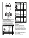
1. Hairpin
2. Front Hanger Pin
3. Rear Links
4. Swivel Bracket
5. Rear Hanger Pin &
Hair Pin
6. Coupling Nut
7. Jam Nut
8. Upper Jam Nut
9. Lower Jam Nut
10. Lift Rod
Figure 9
OM0180
B. Rear Hanger
A. Front Hanger
1
2
3
4
5
7
6
9
8
10